คู่มือผู้ใช้เครื่องเล่นแผ่นเสียง PhotoRobot C850 & C1300
คู่มือการติดตั้งนี้ให้คําแนะนําทางเทคนิคสําหรับการประกอบ การเชื่อมต่อ และการใช้โมดูลเครื่องเล่นแผ่นเสียง PhotoRobot C850 และ C1300 ข้อมูลนี้สนับสนุนการตั้งค่าเริ่มต้นและการใช้งานครั้งแรกของหุ่นยนต์ C850 หรือ C1300 โดยลูกค้า นอกจากนี้ยังอธิบายถึงการประกอบส่วนขยาย Robotic Arm V8 ที่เป็นอุปกรณ์เสริม และการติดตั้งเสายืดไสลด์ที่เป็นอุปกรณ์เสริม
หมายเหตุ ก่อนหน้านี้ PhotoRobot ได้จัดจําหน่าย C1300 ภายใต้ชื่อ Case 1300 ตอนนี้ C1300 จะแทนที่ชื่อรุ่นเดิม
สำคัญ: โปรดอ้างอิง ข้อมูลความปลอดภัยและคำแนะนำของ PhotoRobot เสมอก่อนการติดตั้งด้วยตนเอง การใช้งานครั้งแรก การจัดเก็บ หรือการบริการอุปกรณ์ PhotoRobot
C850 & C1300 ติดตั้งเองและใช้งานครั้งแรก
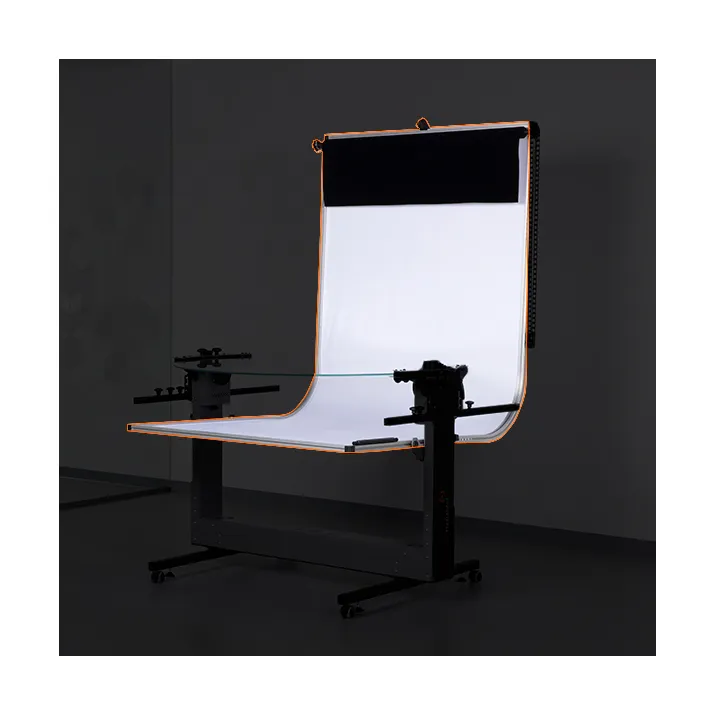
ขอขอบคุณและขอแสดงความยินดีกับการซื้อ PhotoRobot ของคุณ เทคโนโลยี PhotoRobot แสดงถึงประสบการณ์ระดับมืออาชีพ ข้อมูลเชิงลึก และนวัตกรรมในการถ่ายภาพอัตโนมัติมานานหลายทศวรรษ ทุกอย่างตั้งแต่การออกแบบที่แข็งแกร่งและมีสไตล์ไปจนถึงระบบ PhotoRobot แบบแยกส่วน โดยคํานึงถึงธุรกิจของคุณเป็นหลัก ใช้ข้อมูลต่อไปนี้สําหรับการติดตั้งด้วยตนเองและการใช้งานเครื่องเล่นแผ่นเสียง C850 & C1300 เป็นครั้งแรก คู่มือนี้ครอบคลุมคําอธิบายผลิตภัณฑ์ และให้คําแนะนําสําหรับการติดตั้งและการทดสอบ แบบครั้งเดียว
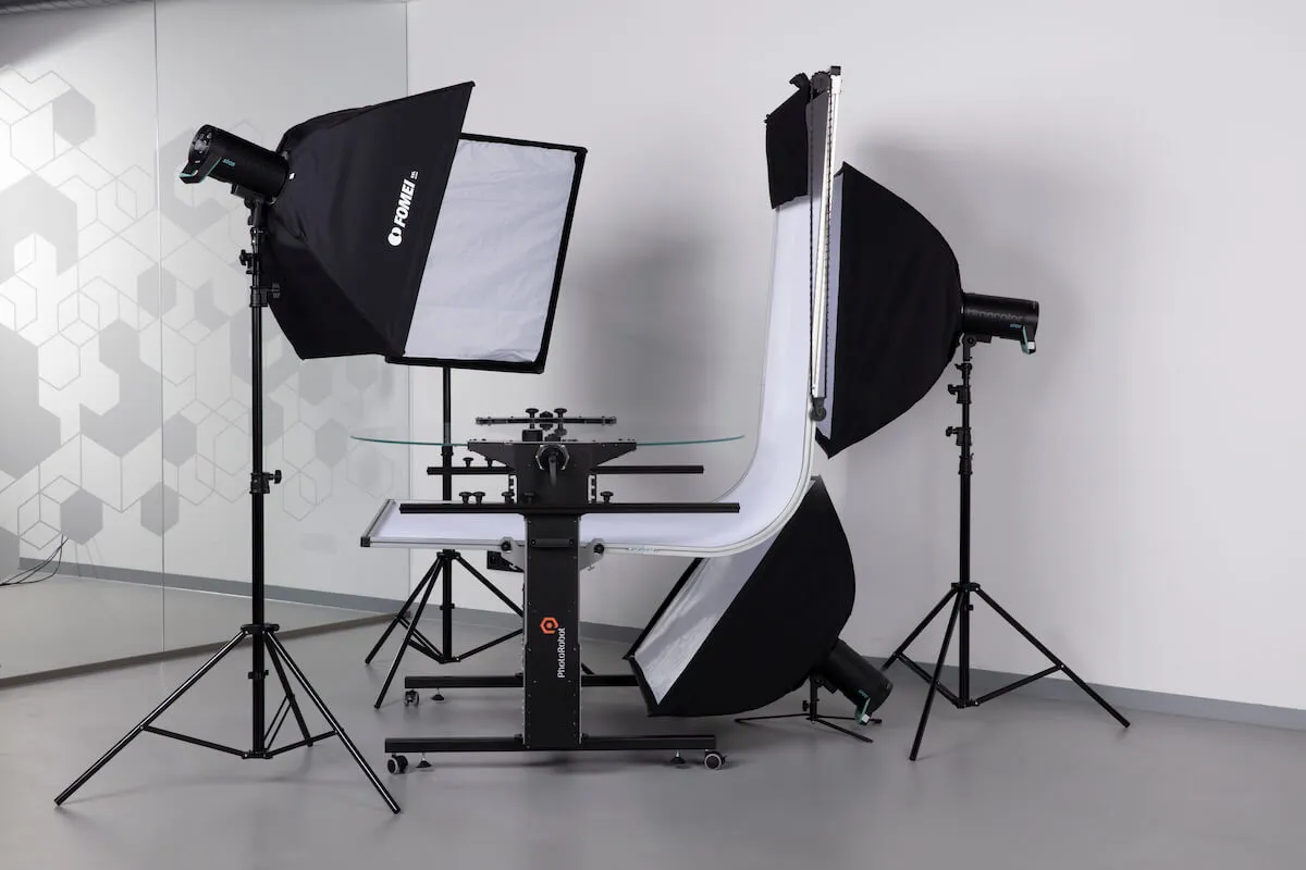
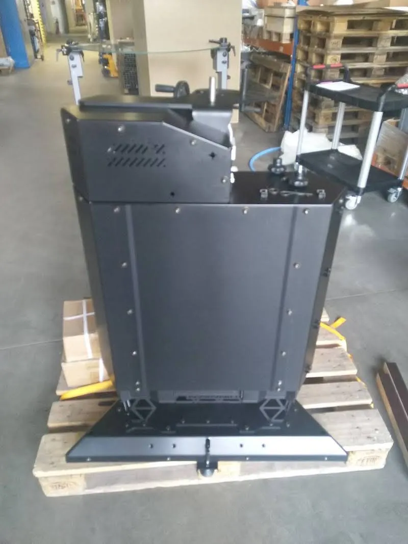
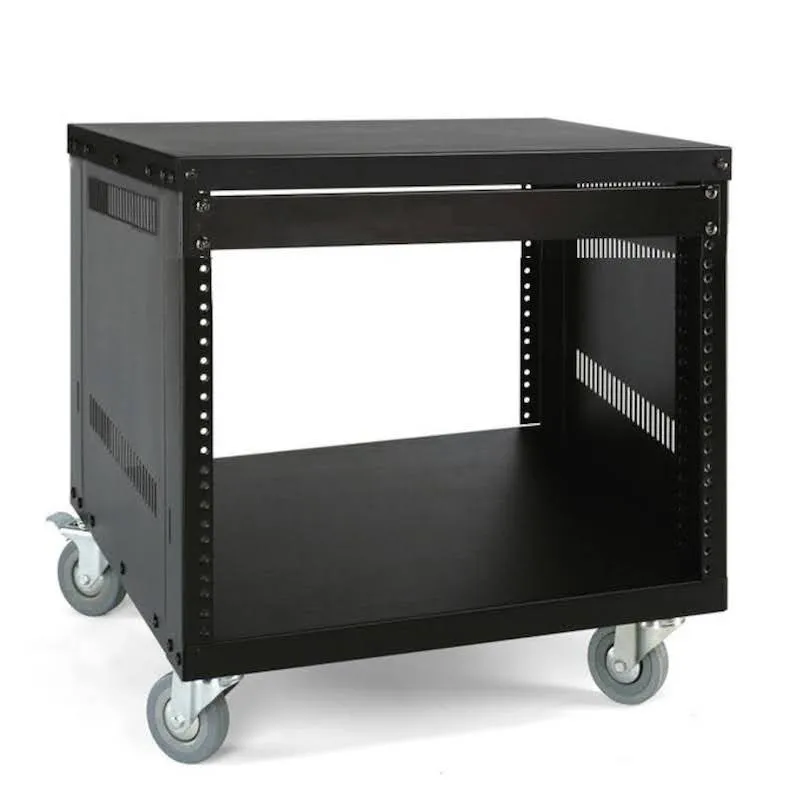
1. รายละเอียดสินค้า C850 & C1300
ในการเปรียบเทียบข้อแตกต่างเพียงอย่างเดียวระหว่างระบบ PhotoRobot C850 และ C1300 คือ C1300 รองรับแผ่นเสียงขนาดต่างๆ (สูงสุด 1300 มม.)
ทั้ง C850 และ C1300 มีตัวเครื่องขนาดเท่ากัน โดยมีโครงเหล็กที่แข็งแรงมีน้ําหนักมากกว่า 100 กก. หนักกว่าการออกแบบอะลูมิเนียมหนัก 70 กก. ของ Case 850 แต่ให้ความเสถียรและประสิทธิภาพที่มากขึ้นในสตูดิโอ แม้ว่าจะมีค่าใช้จ่ายในการพกพาน้อยลงเล็กน้อย แต่การออกแบบที่แข็งแรงกว่าไม่จําเป็นต้องมีสะพานรองรับใต้เครื่องเล่นแผ่นเสียงอีกต่อไป ดังนั้นการออกแบบจึงเปิดกว้างมากขึ้นทําให้มีมุมมากขึ้นสําหรับการจัดแสงวัตถุ
ส่วนประกอบหลักของระบบเครื่องเล่นแผ่นเสียงภาพถ่าย C-Class ได้แก่:
- ชุดควบคุมระบบ (อุปกรณ์ในตัวสําหรับควบคุมโมดูล C-Class)
- ตัวหุ่นยนต์ (โครงเหล็กแข็งแรงพร้อมการออกแบบแบบเปิดเพื่อแสงวัตถุที่เหนือกว่า)
- พื้นหลังผ้ากระจายสีขาว (ติดตั้งกับเครื่องเพื่อถ่ายภาพอัตโนมัติบนพื้นหลังสีขาวบริสุทธิ์)
- ลูกล้อในตัวเพื่อความคล่องตัวในสตูดิโอ
- ความสามารถในการขนส่งที่สะดวกสบายด้วยการเคลื่อนย้ายรถตู้
- การขยายแขนหุ่นยนต์ V8 เสริม (รวมถึงชุดควบคุมและแท่นวางเสริม)
- เสายืดไสลด์สําหรับติดตั้งเสริม
1.1. ภาพรวมอุปกรณ์ - C850, C1300
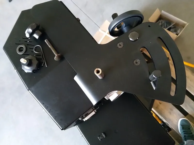
พลังและการควบคุมของเครื่องเล่นแผ่นเสียง C-Class C850 และ C1300 นั้นผ่านชุดควบคุมในตัว ชุดควบคุมจะเปิดระบบและควบคุมการเคลื่อนไหวของหุ่นยนต์ของเครื่องเล่นแผ่นเสียง นอกจากนี้ยังเป็นสิ่งที่ให้พลังงานและควบคุมการขยายแขนหุ่นยนต์ที่เป็นอุปกรณ์เสริมหากใช้กับโมดูล
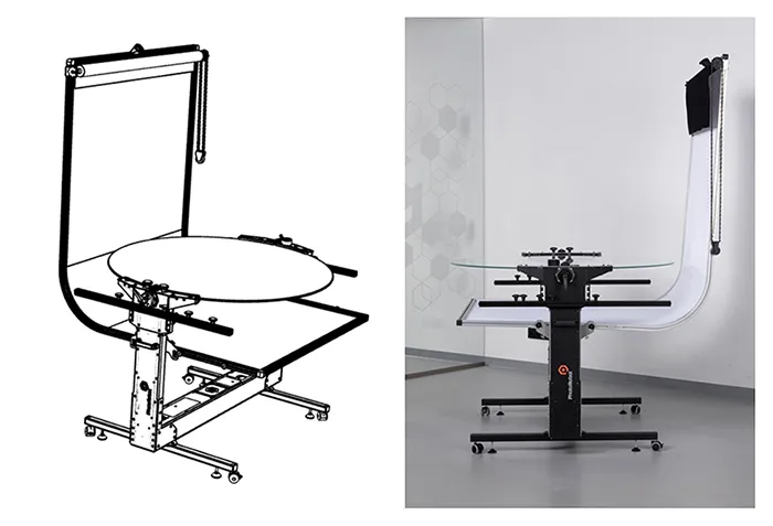
โน้ต: ชุดควบคุมของเครื่องเล่นแผ่นเสียง C-Class มีอยู่ในอุปกรณ์ หากใช้ส่วนขยาย Robotic Arm V8 แขนหุ่นยนต์จะมีชุดควบคุมของตัวเองที่ไม่ได้ติดตั้งในตัว ชุดควบคุมของแขนหุ่นยนต์สามารถวางตําแหน่งในชั้นวาง HD ของอุปกรณ์ C-Class แทน โดยเชื่อมต่อจากแขนไปยังชุดควบคุมแขนผ่านสายมอเตอร์
2. การประกอบหุ่นยนต์ / การเตรียมการใช้งาน
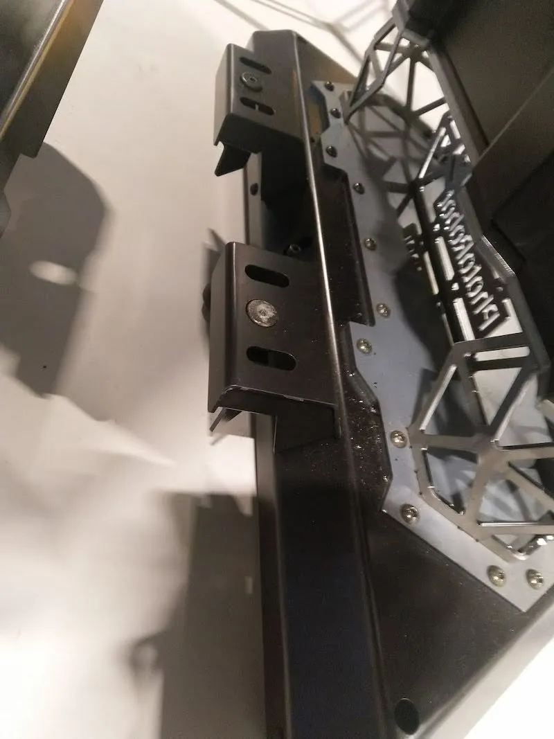
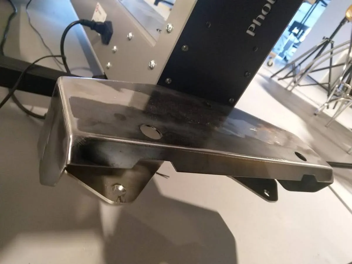
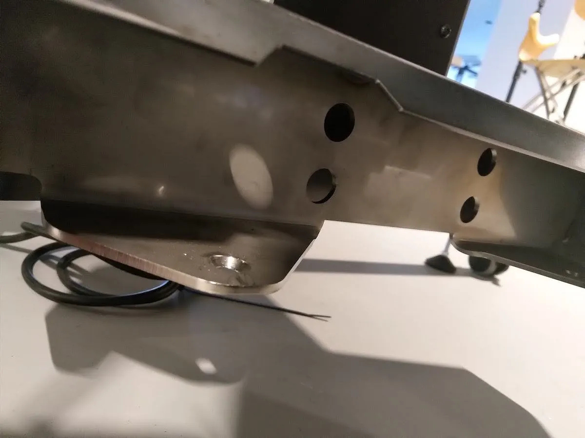
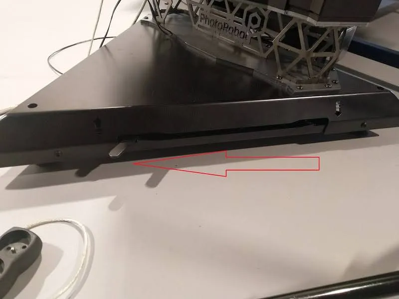
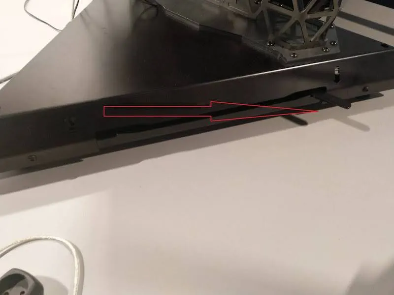
2.1.1. ในการเริ่มการประกอบหุ่นยนต์ ก่อนอื่นให้ค้นหาฟีดและล้อรองรับ จากนั้นจึงติดตั้งแต่ละอันเข้ากับโครงกระดูกของเครื่อง
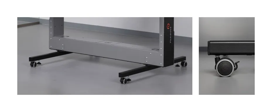
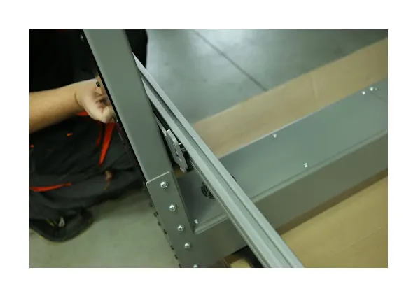
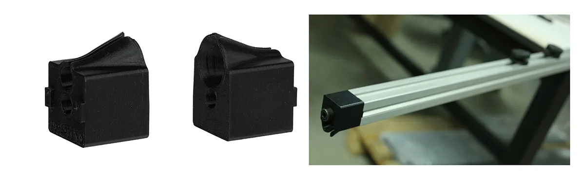
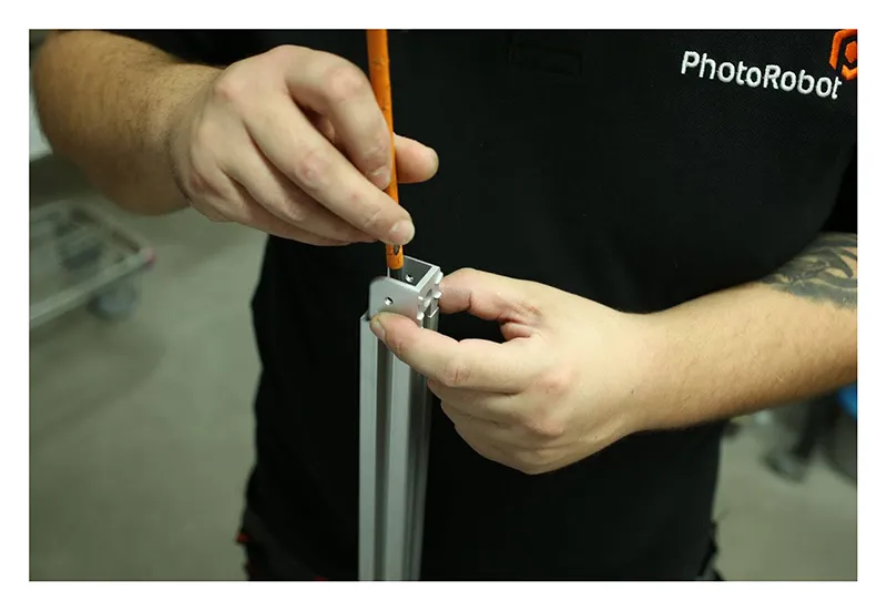
2.1.2. ถัดไป ค้นหาตัวยึดสีดําสองตัว และติดตั้งทั้งสองเข้ากับส่วนแนวตั้งของโครงกระดูก
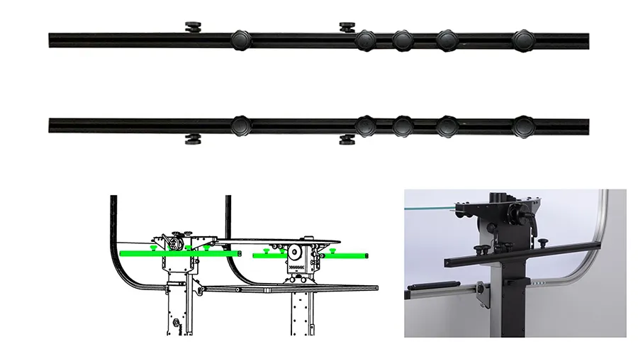
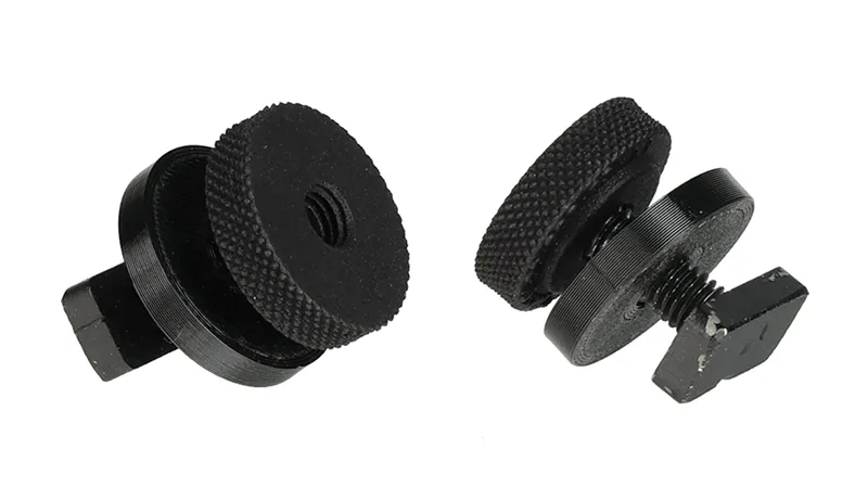
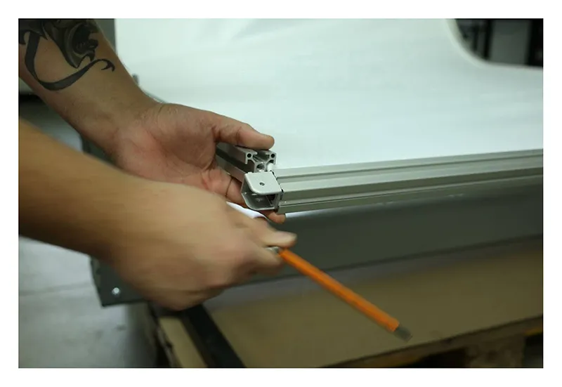
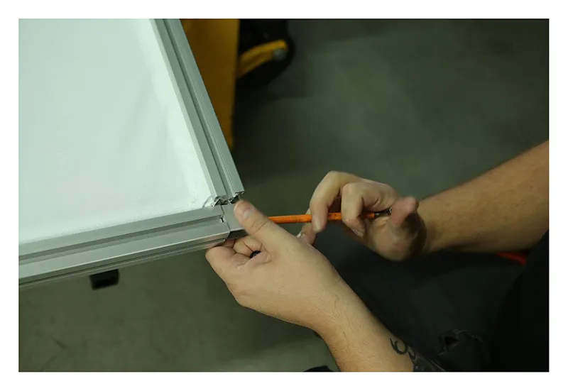
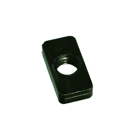
2.1.3. หมายเหตุ ควรใส่และขันสกรูและน็อตพิเศษเข้าไปในรูตามภาพต่อไปนี้
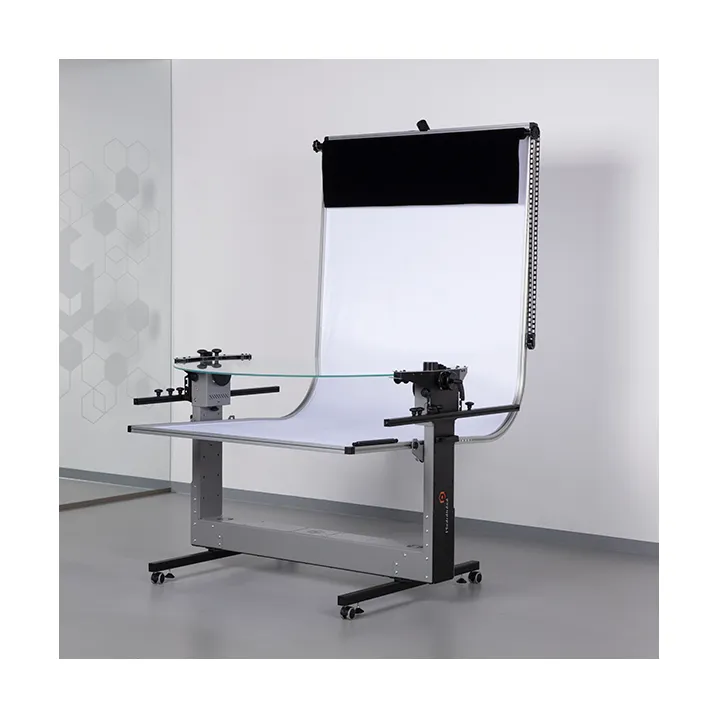
2.2. การประกอบพื้นหลังสีขาว
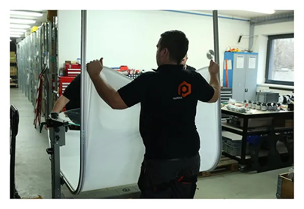
2.2.1. การประกอบพื้นหลังผ้ากระจายสีขาวจําเป็นต้องติดตั้งอุปกรณ์เข้ากับโครงเครื่อง
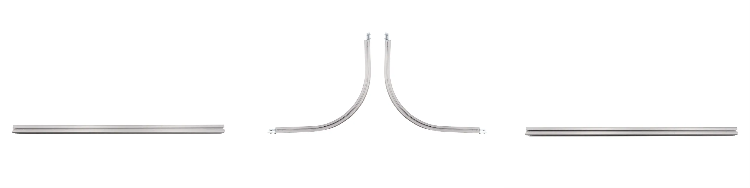
2.2.2. ในการติดตั้งพื้นหลังสีขาว กรอบพื้นหลังมีห้าส่วน:
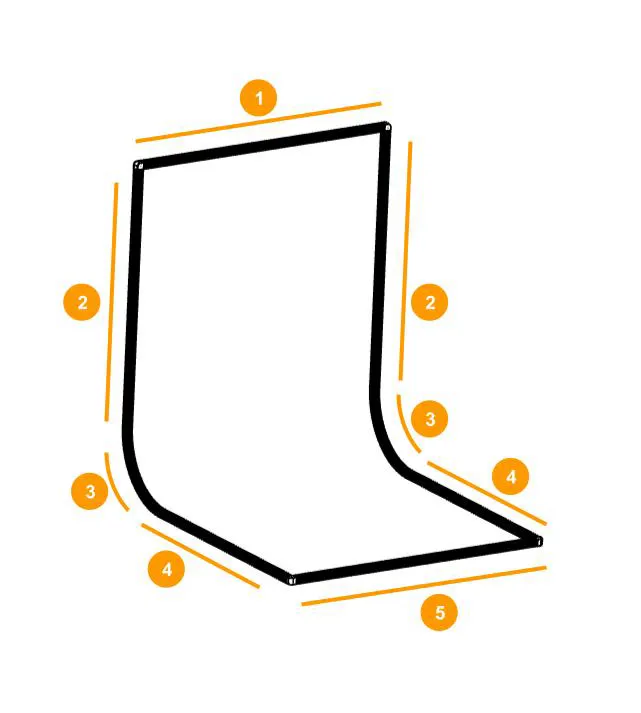
- ส่วนบน (1) - 122 ซม
- ชิ้นส่วนแนวตั้ง (2) - 97 ซม
- ส่วนซุ้มประตู (3)
- ชิ้นส่วนแนวนอน (4) - 82 ซม
- ส่วนหน้า (5) - 122 ซม
2.2.3. ค้นหาสวิตช์เปิดปิดเพื่อระบุด้านหลังของหุ่นยนต์
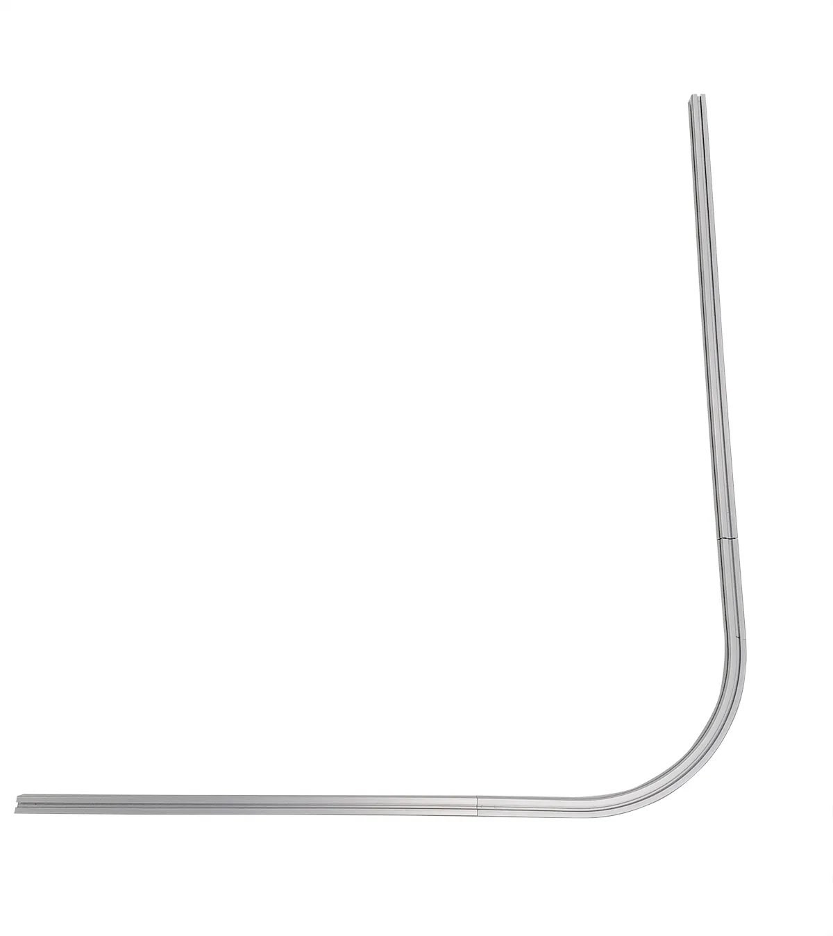
2.2.4. ค้นหาส่วนกรอบพื้นหลังโปรไฟล์โค้งสองส่วน ส่วนเหล่านี้จะทําหน้าที่เป็นหมายเลข (3) จากแผนภาพพื้นหลัง:
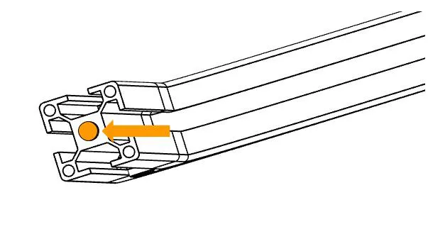
2.2.5. จากนั้นค้นหาข้อต่อแปดตัวสําหรับเชื่อมต่อโปรไฟล์อลูมิเนียม
2.2.6. ดึงชิ้นส่วนโปรไฟล์อลูมิเนียมส่วนโค้งสองส่วน (3) จากแผนภาพกรอบพื้นหลัง จากนั้นติดตั้งข้อต่อในแต่ละส่วน - ซ้ายและขวา ข้อต่อเชื่อมต่อที่ปลายแต่ละด้านของส่วนโค้งในบรรทัด เดียวกัน
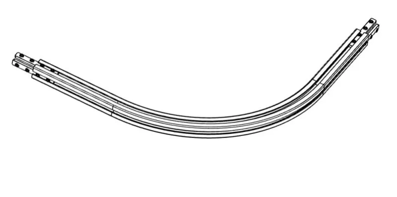
โน้ต: ด้านขวาของซุ้มประตูแสดงในภาพด้านล่าง ข้อต่อควรอยู่ที่ปลายแต่ละด้านในบรรทัดเดียวกัน ภาพด้านล่างแสดงถึงส่วนโค้ง ด้านขวา
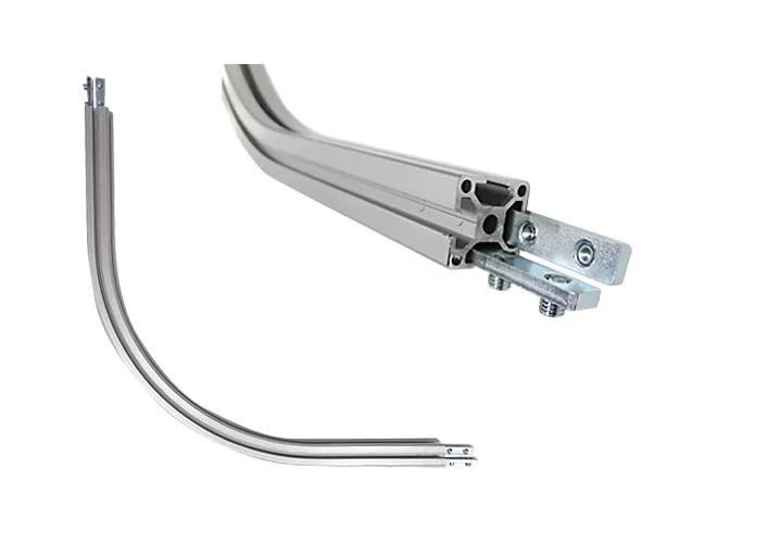
นอกจากนี้: ตรวจสอบให้แน่ใจว่าได้ใส่ข้อต่อตามที่แสดงในภาพด้านบน ข้อต่อเชื่อมต่อที่ปลายแต่ละด้านของส่วนโค้งในบรรทัดเดียวกัน ทําซ้ําขั้นตอนสําหรับส่วนด้านซ้าย
2.2.7. ค้นหาชิ้นส่วนกรอบพื้นหลังโปรไฟล์อลูมิเนียมสองชิ้นยาว 82 ซม. ชิ้นส่วนเหล่านี้จะทําหน้าที่เป็นส่วนแนวนอน (4) จากแผนภาพ พื้นหลัง
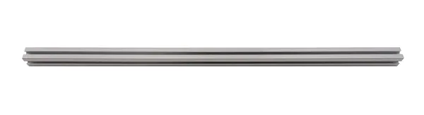
แต่ละส่วนจะเชื่อมต่อกับส่วนโค้งซ้ายและขวาที่ด้านล่าง และจะแสดงถึงส่วนแนวนอนด้านล่าง (4) ของพื้นหลัง
เข้าร่วมโปรไฟล์อลูมิเนียมโค้งและขันสกรูเข้ากับข้อต่อ
2.2.8. ค้นหาชิ้นส่วนกรอบพื้นหลังอะลูมิเนียมอีกสองชิ้นที่มีความยาว 97 ซม. สิ่งเหล่านี้จะทําหน้าที่เป็นส่วนแนวตั้ง (2) จากแผนภาพกรอบพื้นหลังและทําซ้ําขั้นตอนดังแสดงใน 2.2.7
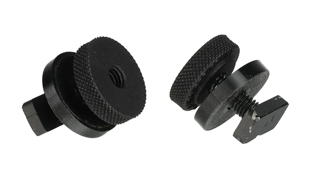
2.2.9. ค้นหาสกรู แหวนรอง และน็อตพิเศษสี่ชุดสําหรับยึดกรอบพื้นหลังเข้ากับหุ่นยนต์
2.2.10. ใส่สกรูสองชุดที่ด้านนอกของแต่ละด้านของชิ้นส่วนแนวนอน (4) ซ้ายและขวาแล้วประกอบเข้าด้วยกัน หมายเหตุ ด้านนอกคือด้านที่มองเห็นข้อต่อ
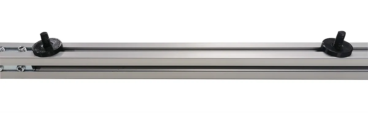
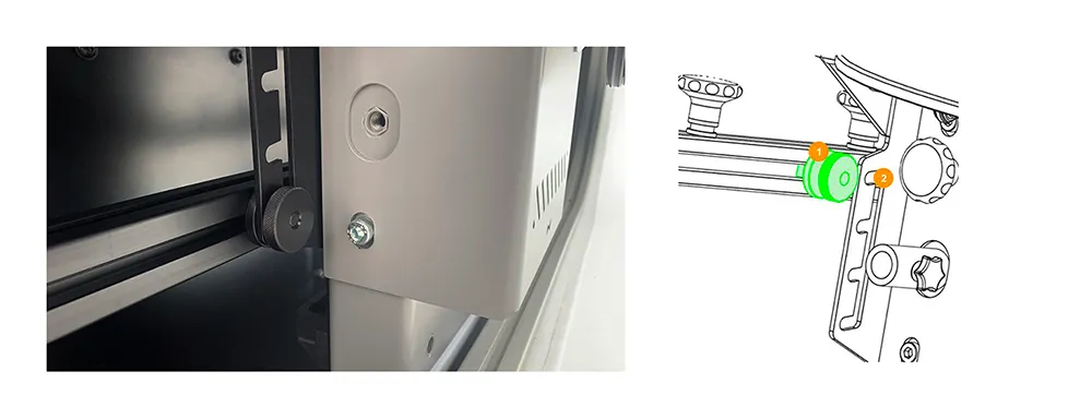
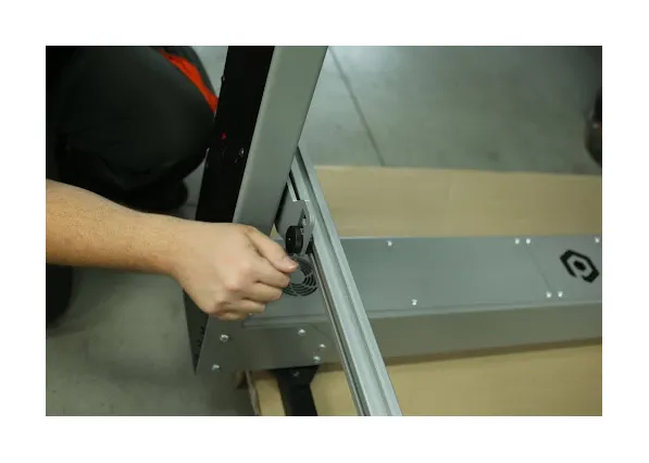
2.2.11. คลายตัวยึดพื้นหลังด้านซ้ายและขวาบนหุ่นยนต์ ตรวจสอบให้แน่ใจว่าได้ติดที่ยึดเข้ากับรูชุดที่สองจากด้านบน
2.2.12. ติดตั้งด้านซ้ายและด้านขวาของเฟรมเข้ากับตัวยึดพื้นหลังบนหุ่นยนต์
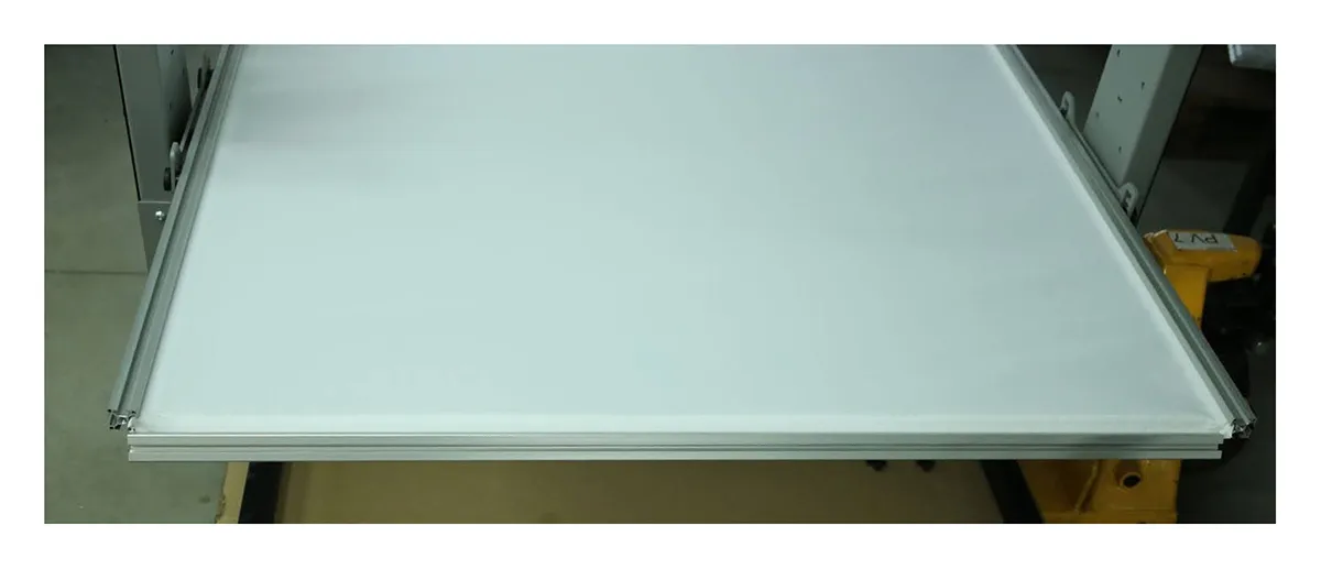
2.2.13. ณ จุดนี้ เฟรมพร้อมสําหรับการแทรกพื้นหลังสีขาว
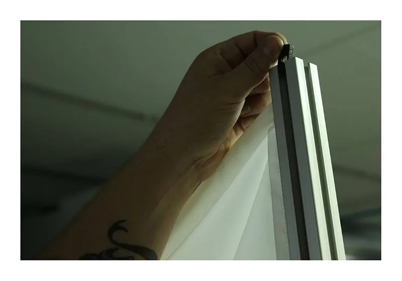
2.2.14. โปรดทราบว่ามีเกลียวที่ปลายเปิดของข้อต่อ
2.2.15. ติดตั้งเครื่องมือเพื่อช่วยในการแทรกขอบพื้นหลังสีขาวลงในส่วนแนวนอน (4) จากแผนภาพพื้นหลัง
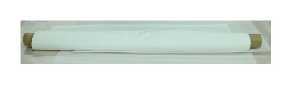
2.2.16. ค้นหากระดาษพื้นหลังสีขาวที่ม้วนแล้วแกะออก
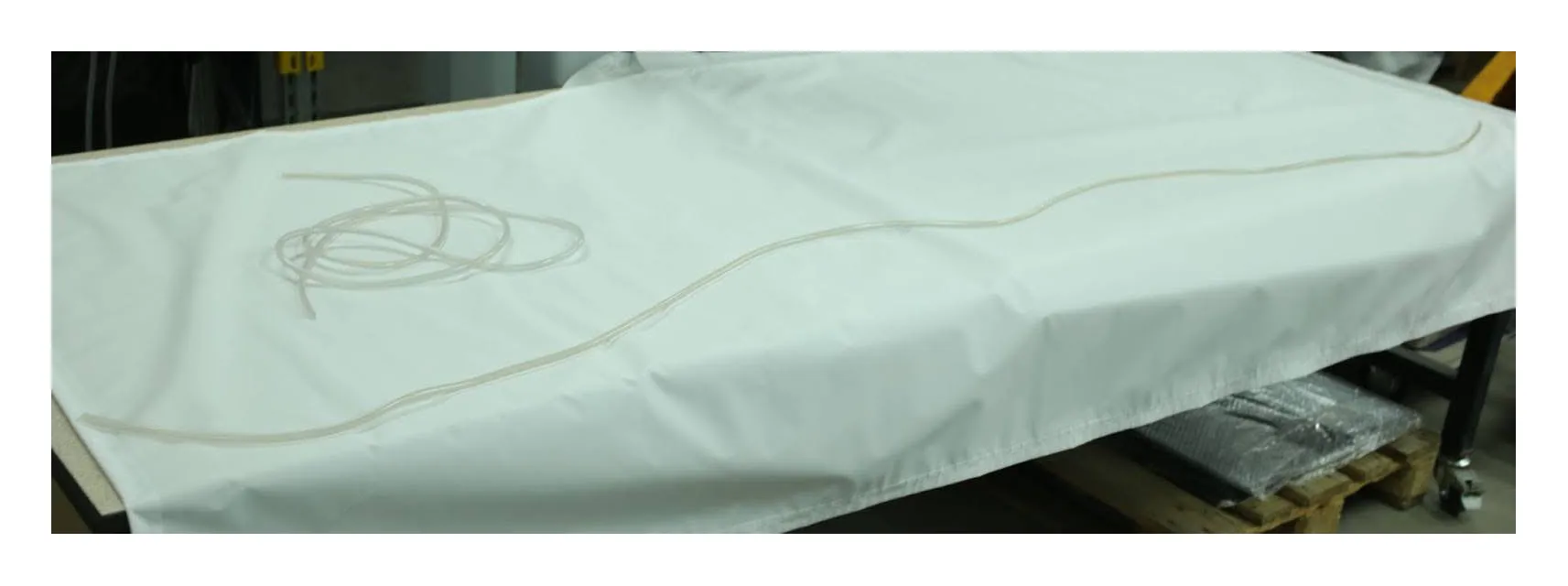
2.2.17. ค้นหาลูกกลิ้งนําพื้นหลังพลาสติก โปรดทราบว่ามีความยาวที่แตกต่างกันสองแบบ
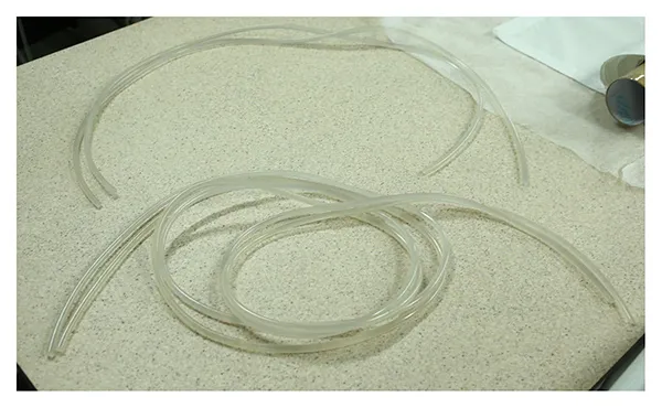
2.2.18. ความยาวของไกด์ต้องสอดคล้องกับด้านที่เหมาะสมของพื้นหลัง
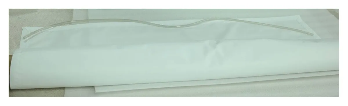
2.2.19. ใส่และป้อนไกด์ทั้งสี่ตัวลงในกระเป๋าที่สอดคล้องกันของพื้นหลังสีขาว
2.2.20. สอดไกด์เข้าไปในกระเป๋าจนสุดจนยื่นออกมาจากปลายทั้งสองด้านของพื้นหลัง
2.2.21. ทําซ้ําขั้นตอนโดยป้อนไกด์ที่สั้นกว่าจนสุดผ่านอีกด้านหนึ่งของพื้นหลัง และทั้งสองด้านที่ยาวกว่าด้วย
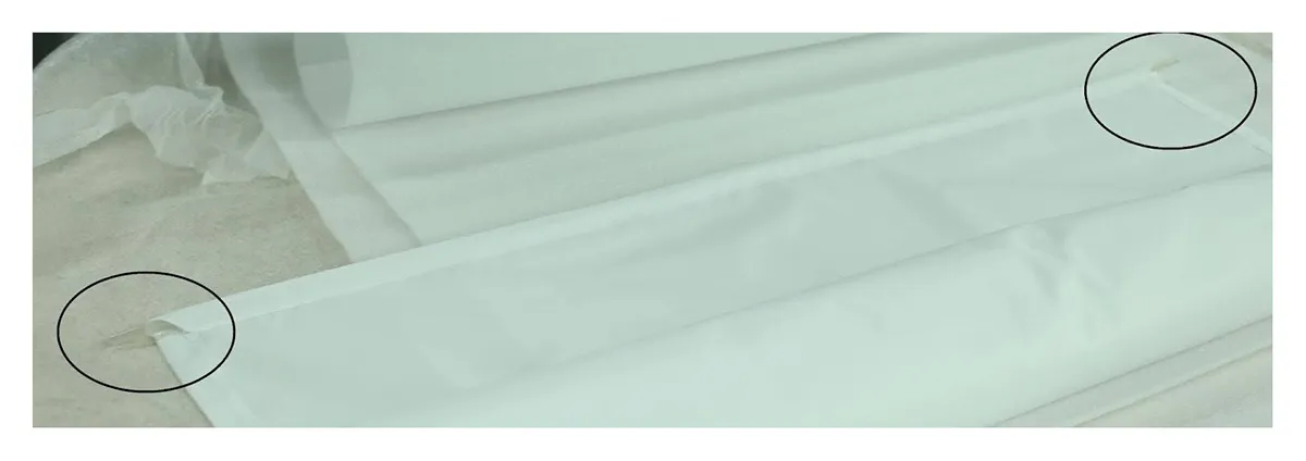
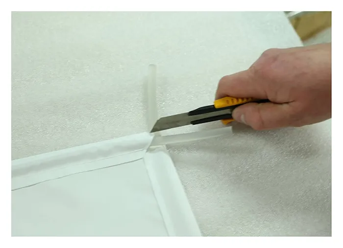
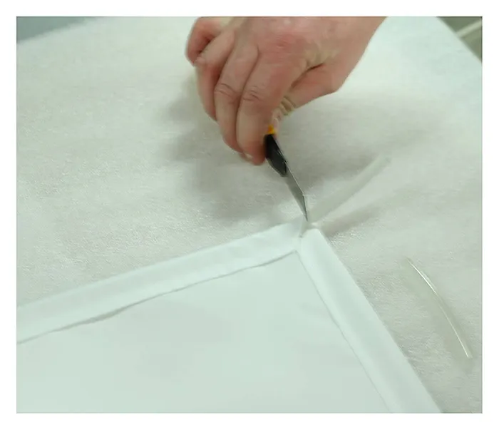
2.2.22. ตรวจสอบให้แน่ใจว่าตัวกั้นพลาสติกที่มุมของพื้นหลังอยู่ในตําแหน่งที่ถูกต้อง
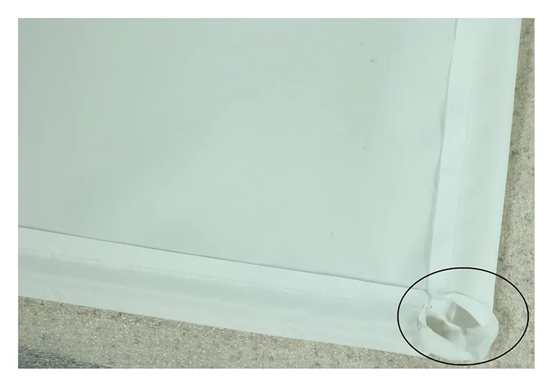
2.2.23. หากตัวกั้นพลาสติกยื่นออกมาจากมุมมากเกินไป ให้ตัดตัวกั้นให้มีความยาวที่เหมาะสม
2.2.24. ค้นหาด้านล่างของพื้นหลังสีขาว
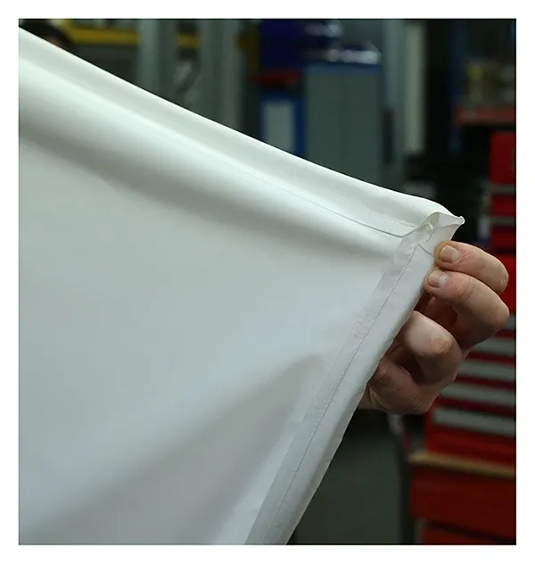
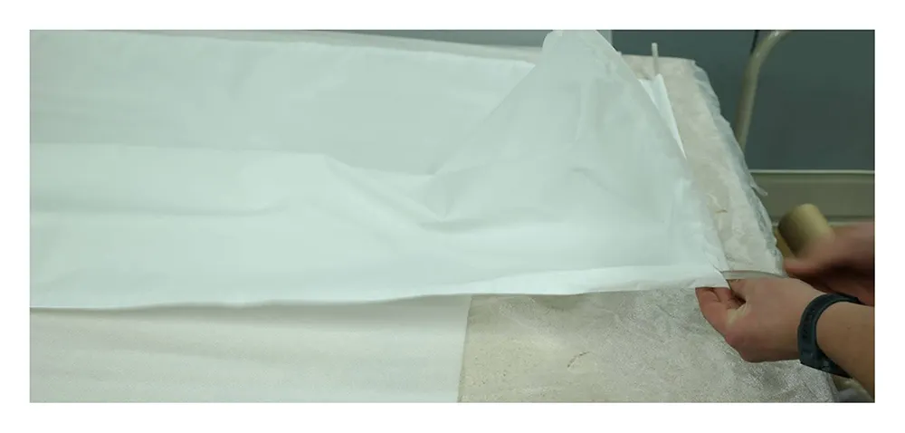
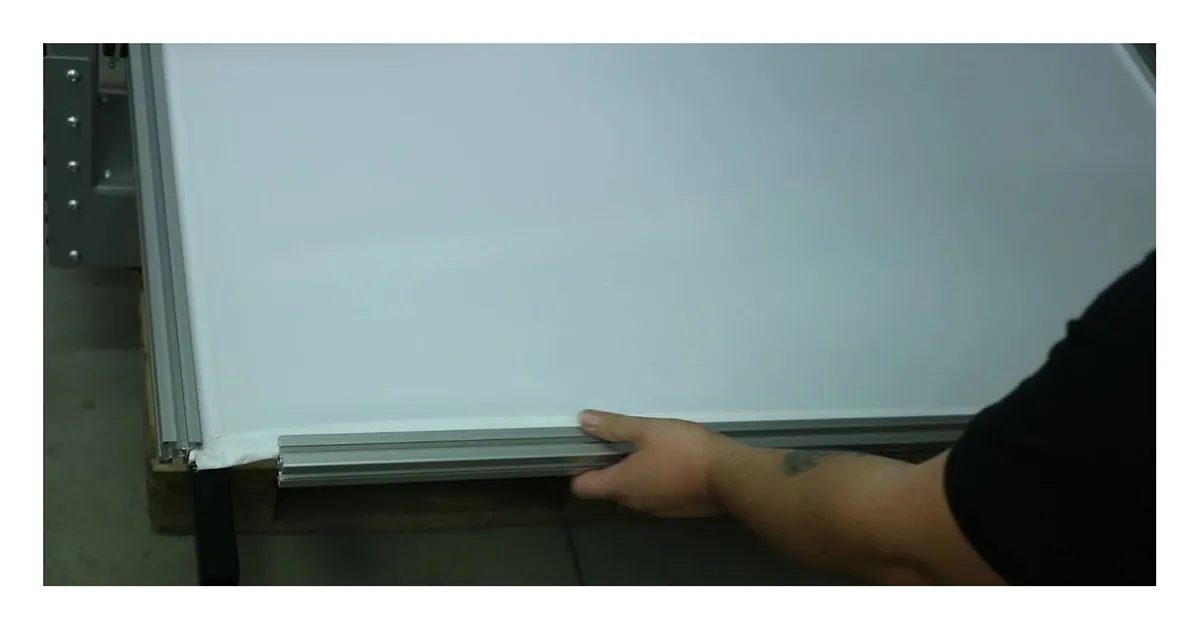
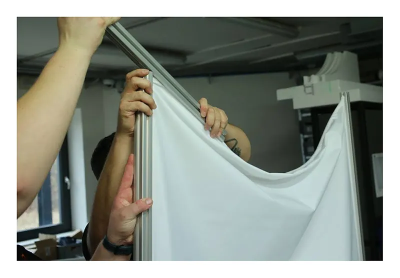
2.2.25. แทรกพื้นหลังลงในเฟรมดังนี้
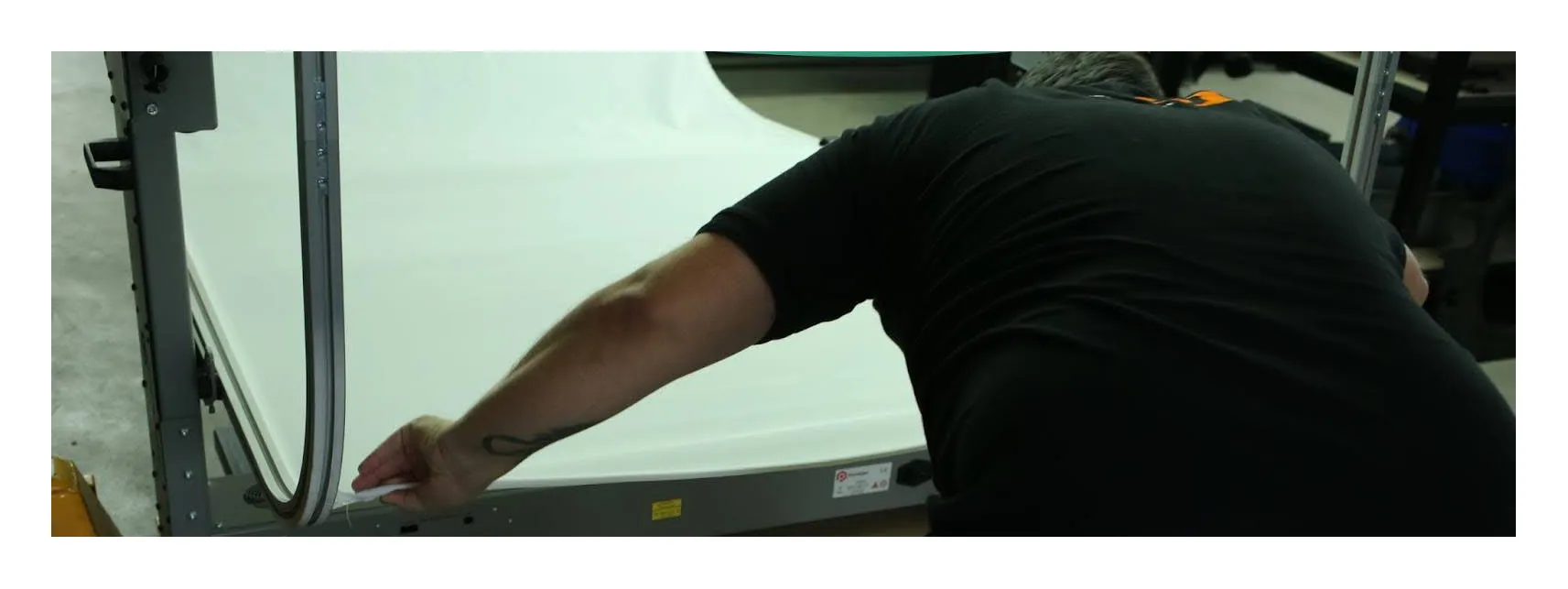
2.2.26 จากนั้น ถอดเครื่องมือสําหรับป้อนขอบพื้นหลังสีขาวลงในโปรไฟล์ และเลื่อนอลูมิเนียมโปร file (5) ในแผนภาพลงบนพื้นหลังสีขาวที่ขอบด้านหน้า
2.2.27. จากนั้นค้นหาข้อต่อสี่มุม
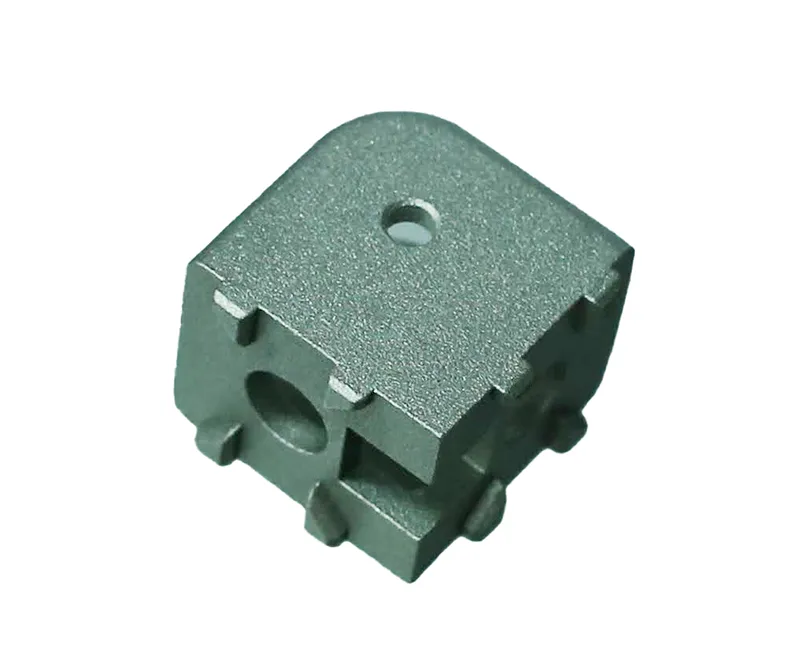
2.2.28. ยึดข้อต่อสองตัวโดยใช้สกรูที่ให้มากับขอบด้านหน้าของกรอบพื้นหลัง
2.2.30. ถัดไป ให้ค้นหาน็อตสี่เหลี่ยมสี่ตัวสําหรับประกอบชิ้นส่วนแนวตั้ง
2.2.29. ใส่น็อตสองตัวเข้าไปในส่วนแนวตั้งด้านขวา และอีกสองตัวเข้าไปในส่วนแนวตั้งด้านซ้าย
2.2.30. เตรียมส่วนบนของเฟรมเพื่อเชื่อมต่อกับพื้นหลังสีขาว
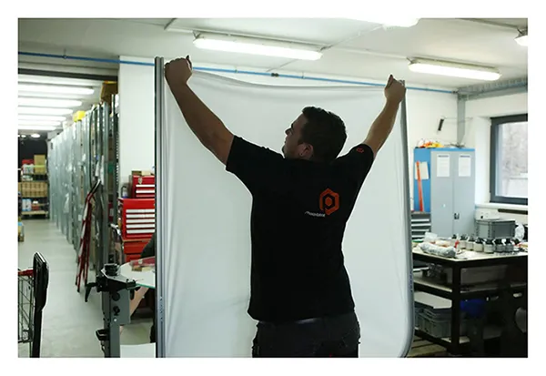
2.2.31. แทรกส่วนบนของเฟรมลงในพื้นหลังสีขาว
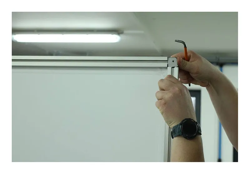
2.2.32. ใส่น็อตเข้าไปในเฟรม เลื่อนและขันสกรูเลเซอร์ด้านบนเข้าไปในน็อต แล้วจัดตําแหน่งไว้ที่ส่วนแนวตั้งตรงกลาง
2.2.33. ติดตั้งข้อต่อมุมสุดท้ายที่เหลืออยู่ที่มุมบนขวาและซ้ายของเครื่อง
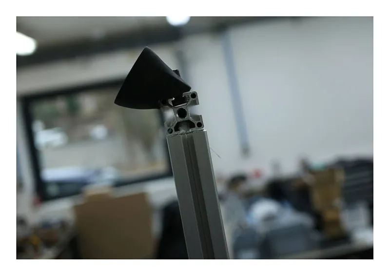
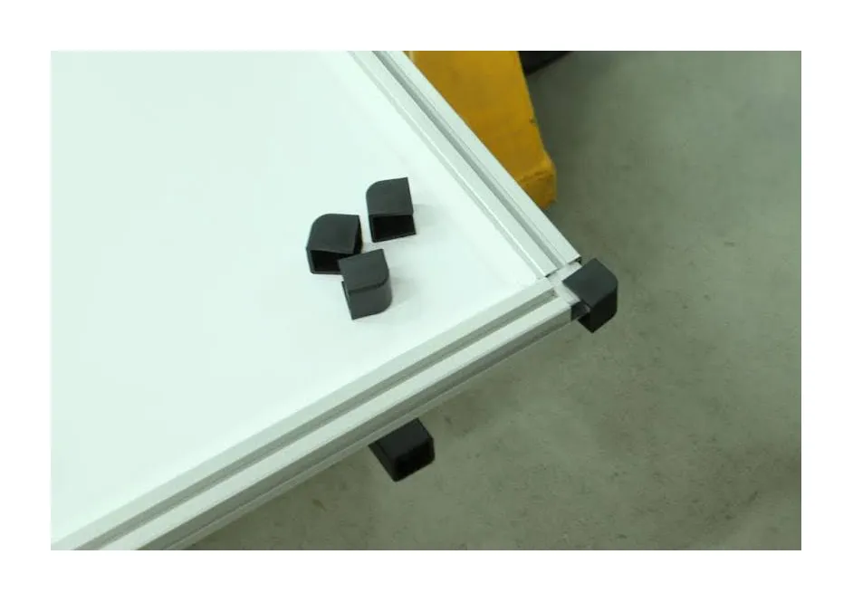
2.2.34. ค้นหาตัวป้องกันมุมพลาสติกสี่ตัว และวางไว้ที่มุมเฟรมทั้งสี่
2.2.35. หาที่ยึดพื้นหลังสีดําสองตัวและสกรูสี่ตัว แล้วยึดเข้ากับเฟรมโดยใช้น็อตสี่เหลี่ยมที่เตรียมไว้ล่วงหน้า
2.2.36. สุดท้าย ติดตั้งพื้นหลังสีดําเข้ากับส้อม จากนั้นเพิ่มโซ่และน้ําหนัก
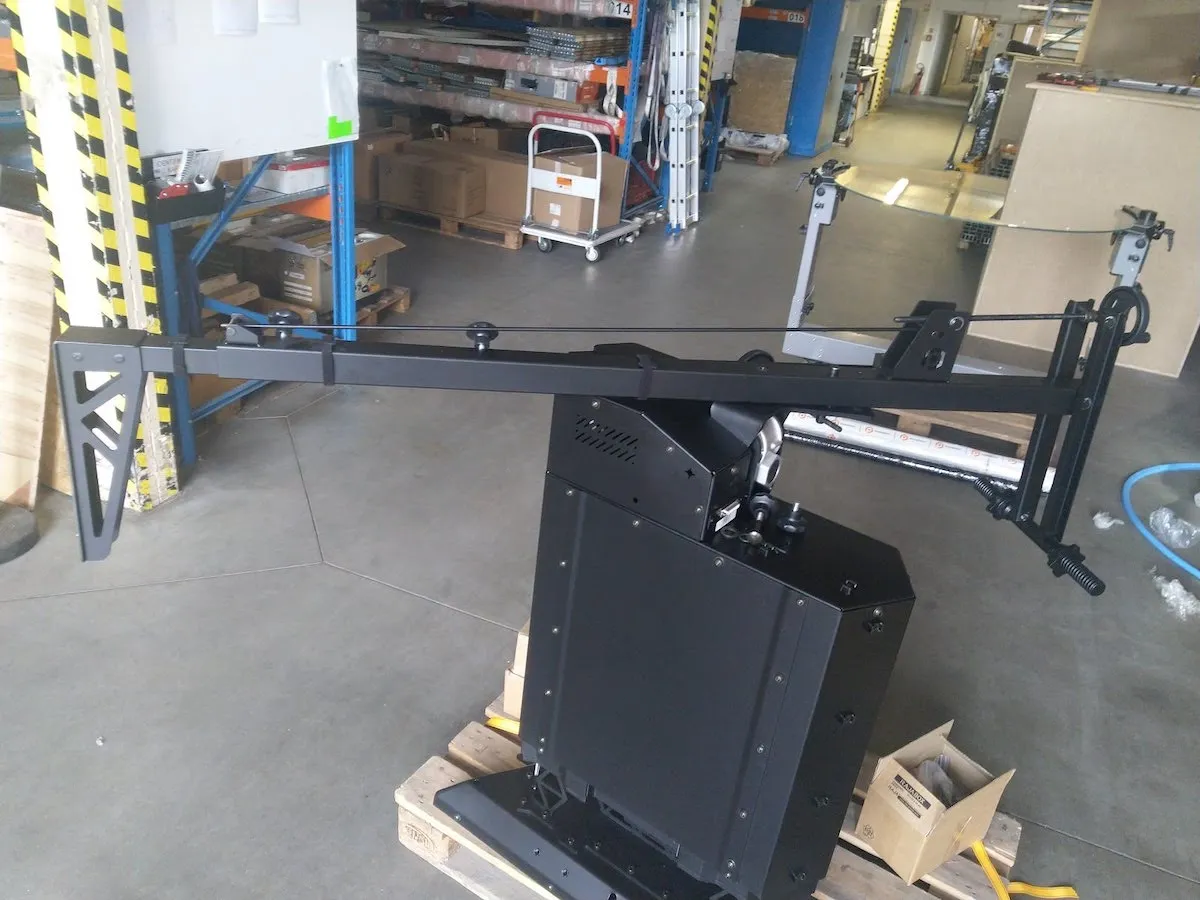
2.3. การเตรียมแขนหุ่นยนต์ V8 (อุปกรณ์เสริม)
2.3.1. หาก PhotoRobot Robotic Arm V8 มาพร้อมกับหุ่นยนต์ C-Class ให้ใช้คําแนะนําต่อไปนี้ในการประกอบ หมายเหตุ สําหรับข้อมูลทางเทคนิคเพิ่มเติมเกี่ยวกับการติดตั้งด้วยตนเองและการใช้งาน Robotic Arm V8 เป็นครั้งแรก โปรดดูคู่มือการติดตั้ง Robotic Arm V8
ขึ้นอยู่กับการกําหนดค่า Robotic Arm V8 สามารถมีด้ามสั้นหนึ่งก้านยาวหนึ่งก้านหรือทั้งด้ามสั้นและยาว
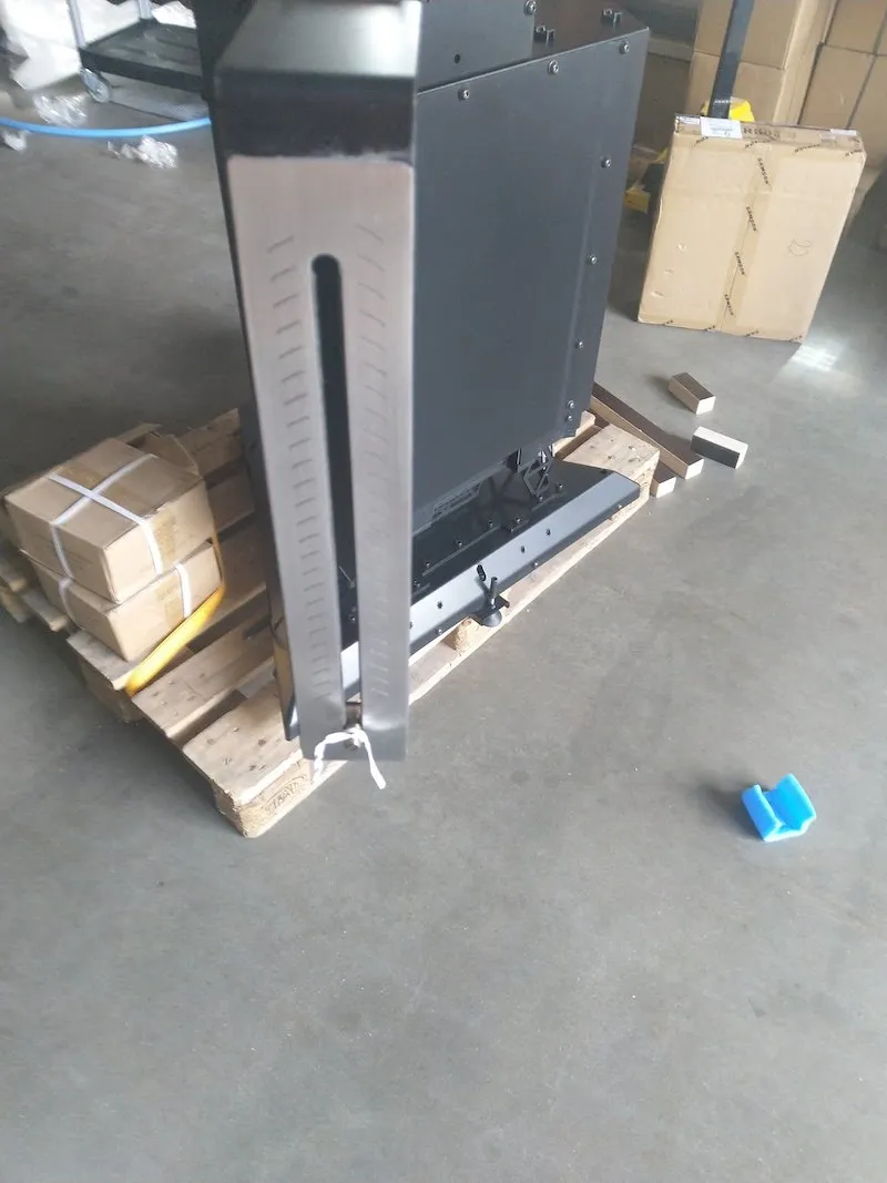
2.3.2. นําก้านและตัวหุ่นยนต์ออกจากบรรจุภัณฑ์
2.3.3. เตรียมส่วนบนของ Arm V8 เพื่อติดตั้งด้าม
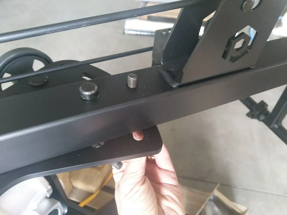
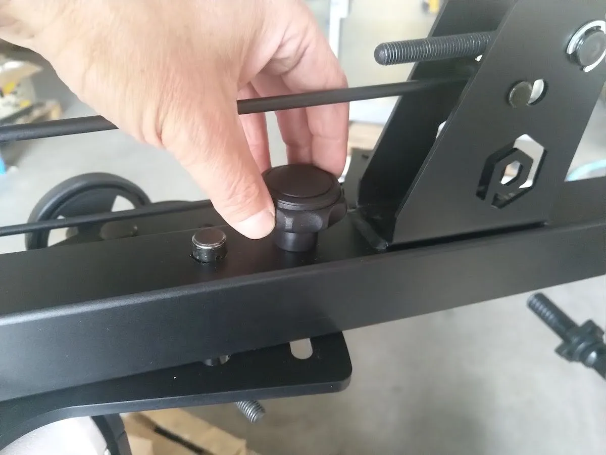
2.3.4. วางด้ามเข้ากับแขน
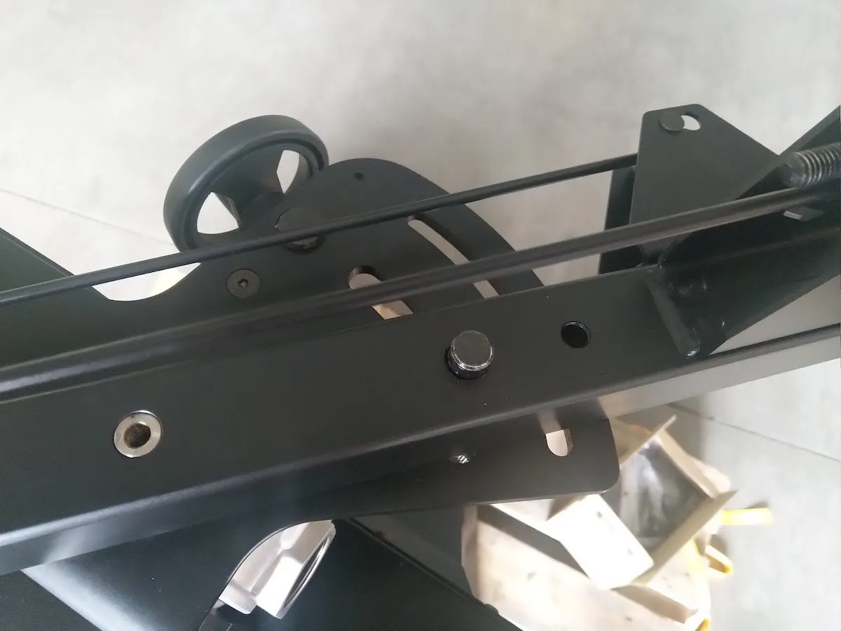
2.3.5. ยึดชิ้นส่วนป้องกันทั้งหมดให้แน่นในตําแหน่งที่เกี่ยวข้อง
2.3.6. ค้นหากล่องของหัวเกียร์ Manfrotto และเตรียมหัวสําหรับติดตั้ง
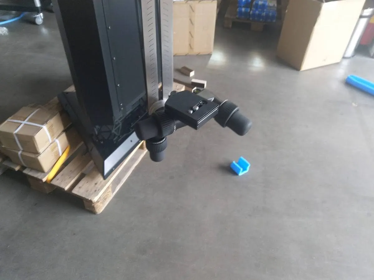
2.3.7. ถอดเชือกสีขาวออกจากสกรูที่ปลายด้าม Arm V8
2.3.8. ติดหัวเฟือง Manfrotto โดยขันเข้ากับด้าม
2.3.9. ปรับหัว Manfrotto จนได้ระดับ
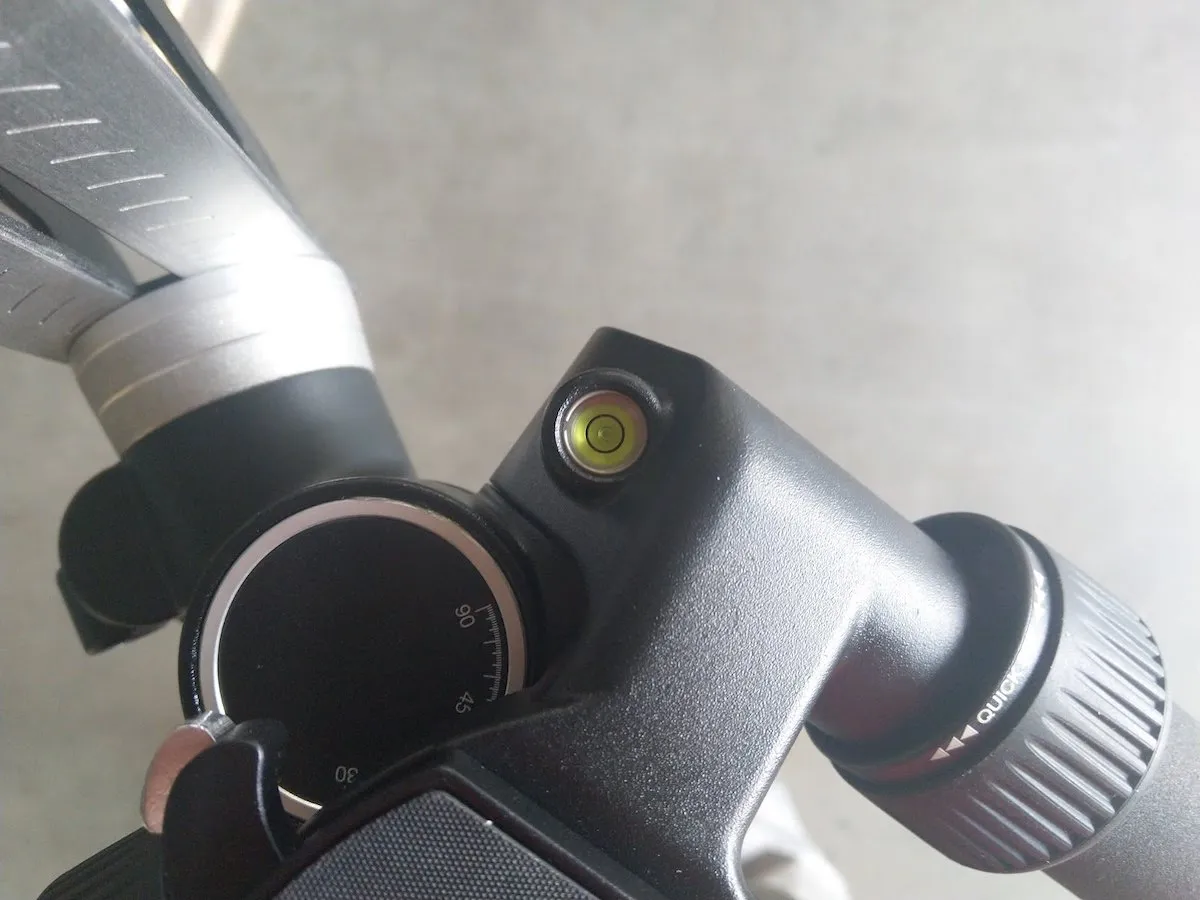
2.3.10. ติดตั้งกล้องเข้ากับหัว Manfrotto และเพิ่มน้ําหนักลงบนด้านตรงข้ามของด้าม น้ําหนักต้องชดเชยน้ําหนักของกล้อง
2.3.11. น้ําหนักของกล้องควรมีชัยเล็กน้อยเพื่อกดสวิตช์ปลายเมื่ออยู่ในตําแหน่งศูนย์องศา
2.3.12. ติดตั้งชิ้นส่วนกลไกการเชื่อมต่อสองส่วนเข้ากับ Arm V8
2.3.13. ติดตั้งส่วนเชื่อมต่อเข้ากับ C850 หรือ C1300
2.3.14. เลื่อนคันโยกไปทางซ้ายเพื่อยก Arm V8 ขึ้นแล้วเลื่อน
2.3.15. เชื่อมต่อ Arm V8 เข้ากับ C850 หรือ C1300
2.3.16. เลื่อนคันโยกไปทางขวาเพื่อลด Arm V8 และเชื่อมต่ออุปกรณ์ให้แน่น
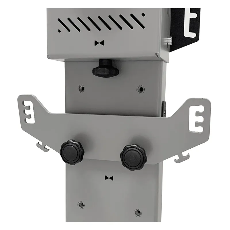
2.3.17. ค้นหาเคสชั้นวาง HD ที่พับอยู่ในกล่องการ์ตูน
2.3.18. ประกอบเคสแร็ค HD
2.3.19. ติดตั้งชุดควบคุมสําหรับ Arm V8 จากนั้นติดตั้งเราเตอร์และเต้ารับไฟฟ้าเข้ากับเคสแร็ค เชื่อมต่อพอร์ตสุดท้าย (พอร์ตที่มีหมายเลขสูงสุด) ของเราเตอร์กับอินเทอร์เน็ต พอร์ตเราเตอร์อื่นๆ ทั้งหมดเชื่อมต่อกันและทํางานเป็นสวิตช์บนไซต์ LAN ที่เชื่อมต่อชุดควบคุม หุ่นยนต์ C-Class และคอมพิวเตอร์ สุดท้าย ต่อสายมอเตอร์สีเทาเข้มเข้ากับ Arm V8 ที่ด้านหนึ่ง และชุดควบคุมที่ติดตั้งในชั้นวางอีกด้านหนึ่ง
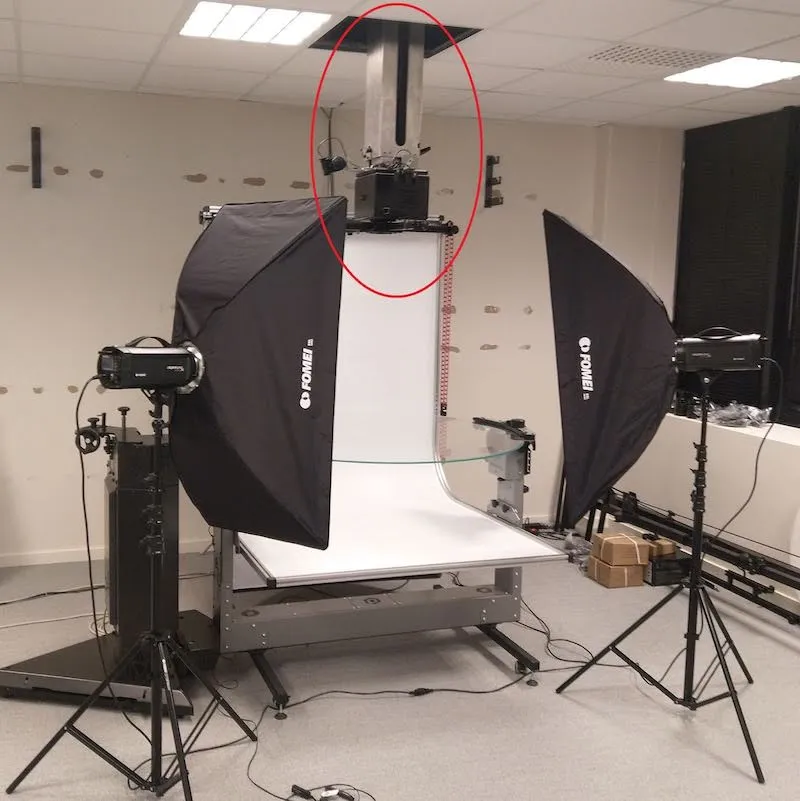
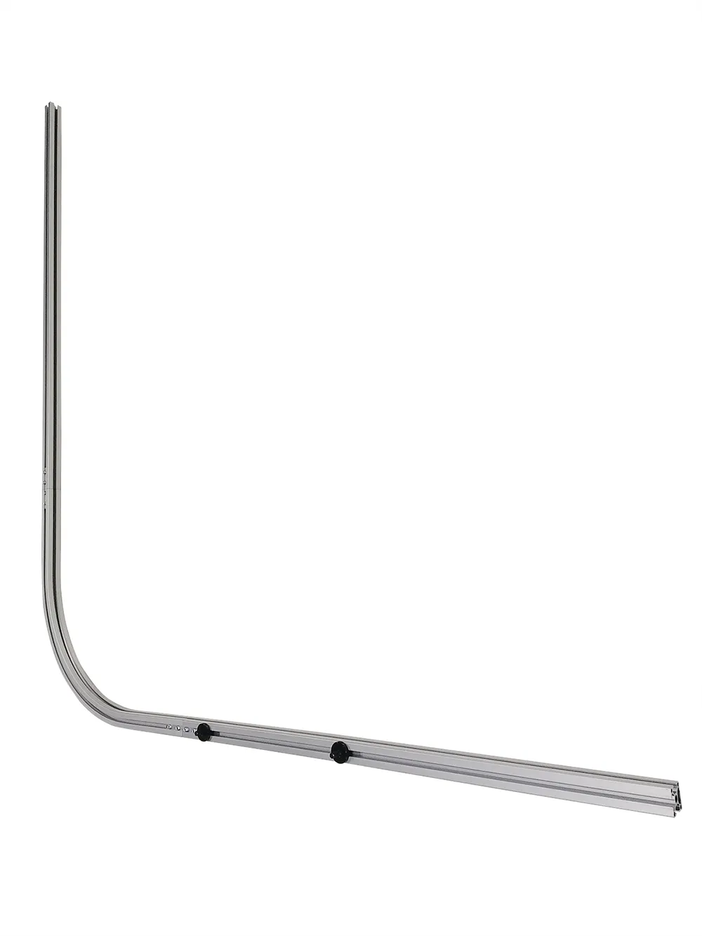
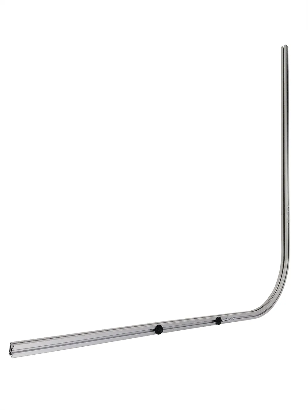
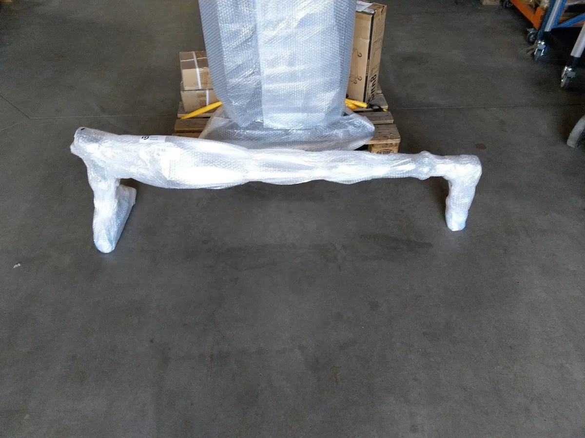
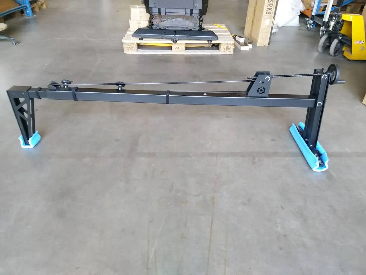
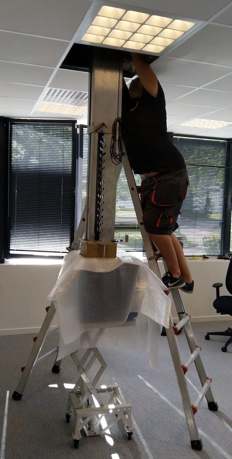
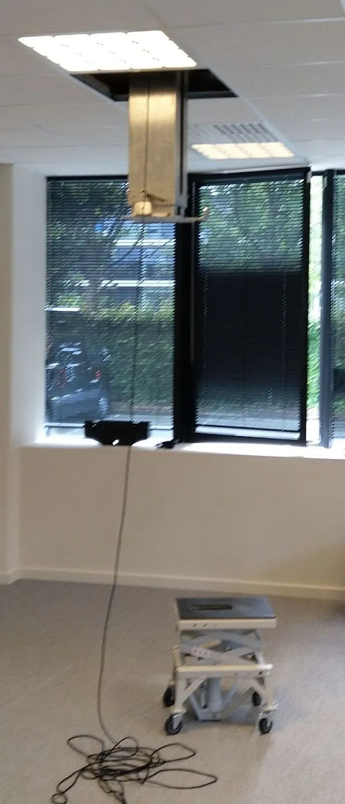
2.4. การติดตั้งเสายืดไสลด์ (อุปกรณ์เสริม)
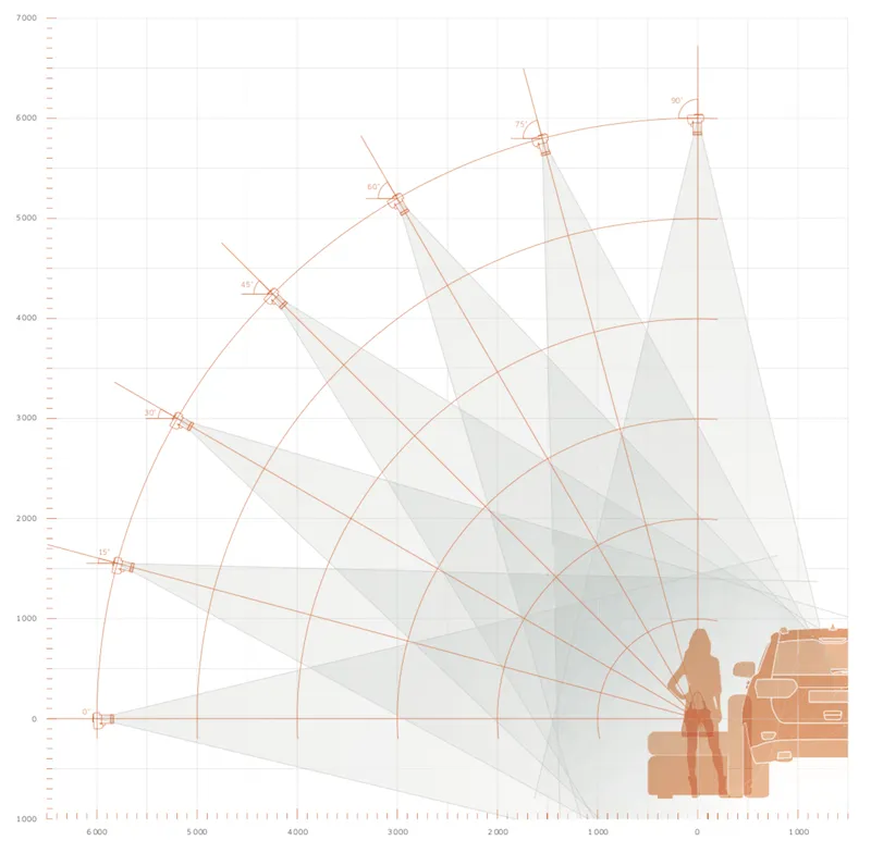
2.4.1. การกําหนดค่าบางอย่างจะรวมถึงเสายืดไสลด์สําหรับติดตั้งอุปกรณ์ PhotoRobot Cube ที่เป็นอุปกรณ์เสริมกับเพดานเหนือโมดูล C-Class ในกรณีเหล่านี้ เสายืดไสลด์จะถูกติดตั้งบนเพดานเพื่อยึดลูกบาศก์ไว้เหนือหุ่นยนต์ C-Class วิธีนี้ช่วยให้สามารถแขวนรายการ (หรือบางส่วนของรายการ) เหนือเครื่องเล่นแผ่นเสียงโดยใช้ Cube ที่มีสายไนลอนเพื่อจัดฉากและหมุนรายการสําหรับการถ่ายภาพ 360 องศา ในขณะเดียวกัน Cube สามารถซิงค์การหมุนของรายการที่ถูกระงับกับการหมุนของเครื่องเล่นแผ่นเสียง การเคลื่อนไหวของหุ่นยนต์ตัวอื่น ไฟสตูดิโอ และการจับภาพด้วยกล้อง
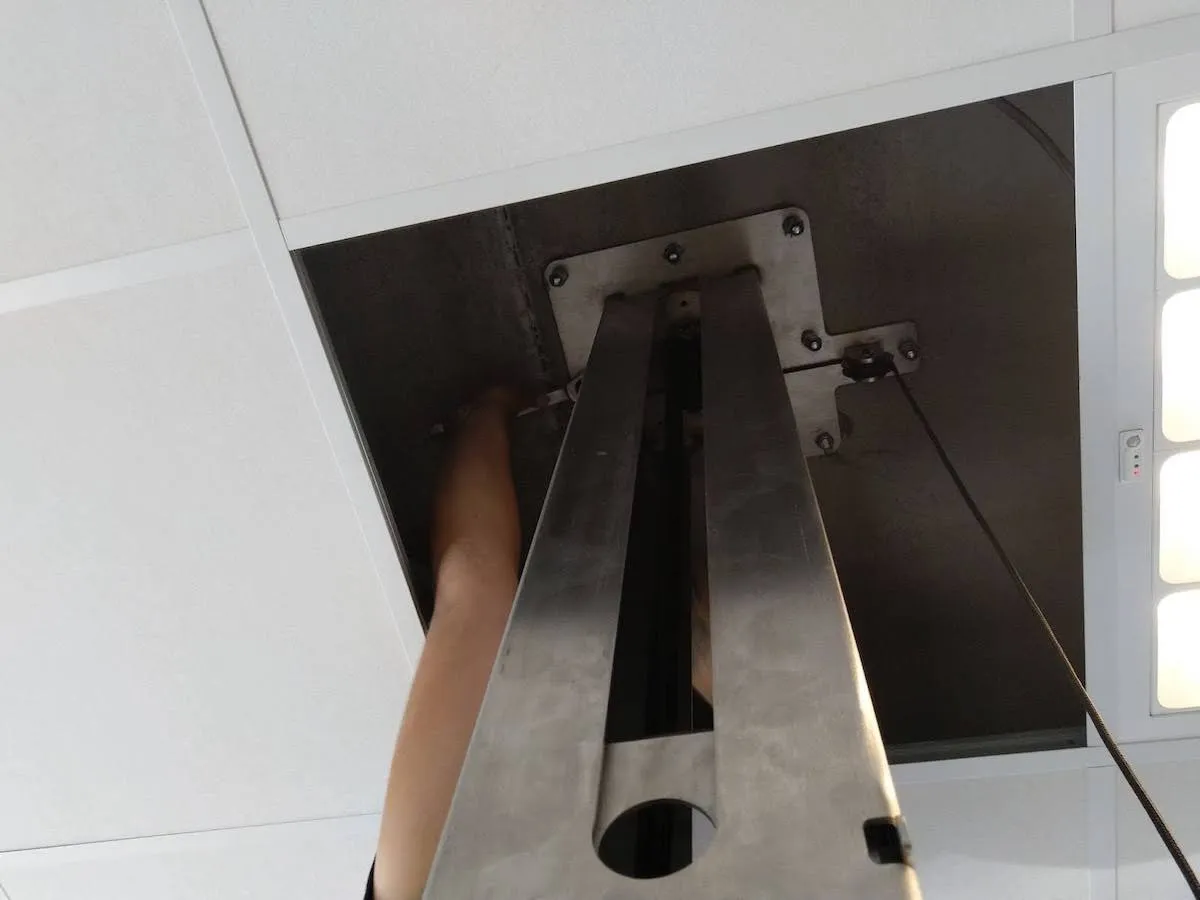
2.4.2. เสายืดไสลด์ต้องใช้เพดานคอนกรีต และยึดติดกับเพดานโดยใช้แท่งเกลียว 8 ชิ้น จําเป็นต้องเจาะ 8 รูบนเพดานและให้แม่นยําเมื่อเจาะเพื่อสังเกตระยะห่างที่แน่นอนระหว่างรู เตรียมสารเคมีพุกล่วงหน้า ใช้อุดรูและใส่แกนเกลียวเข้าไป ทําซ้ําขั้นตอนนี้สําหรับทั้ง 8 ชิ้น
2.5. การเชื่อมต่อกล้อง
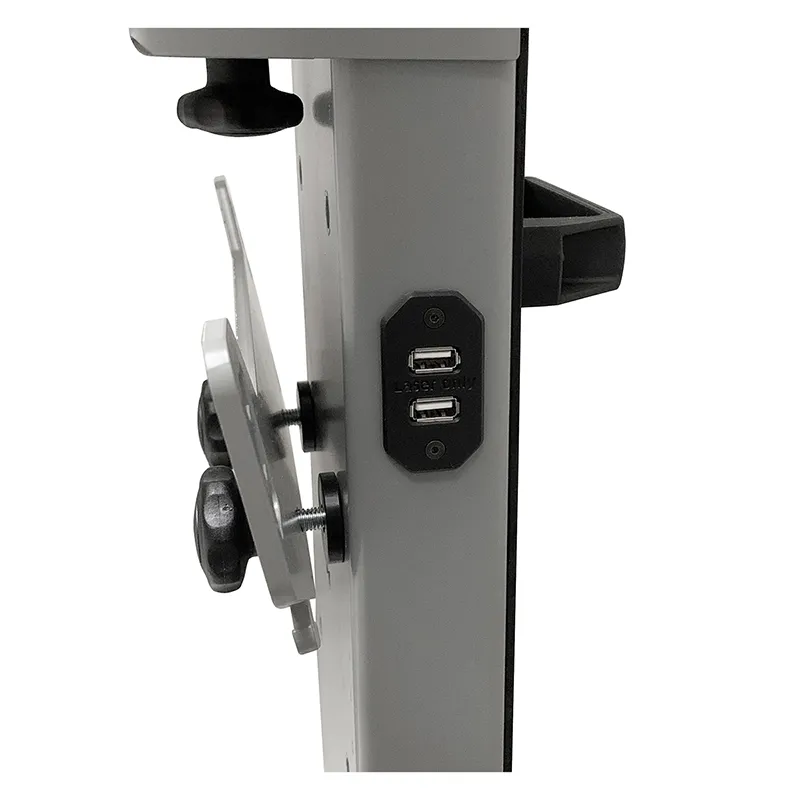
2.5.1. ในการเชื่อมต่อกล้องกับคอมพิวเตอร์ จําเป็นต้องใช้สาย USB ที่เข้ากันได้ โปรดทราบว่าประเภทของตัวเชื่อมต่อจะแตกต่างกันไปตามรุ่นของกล้อง ขอแนะนําให้ใช้ส่วนขยาย USB ที่ใช้งานอยู่หากความยาวสายเคเบิลยาวกว่า 3 เมตร
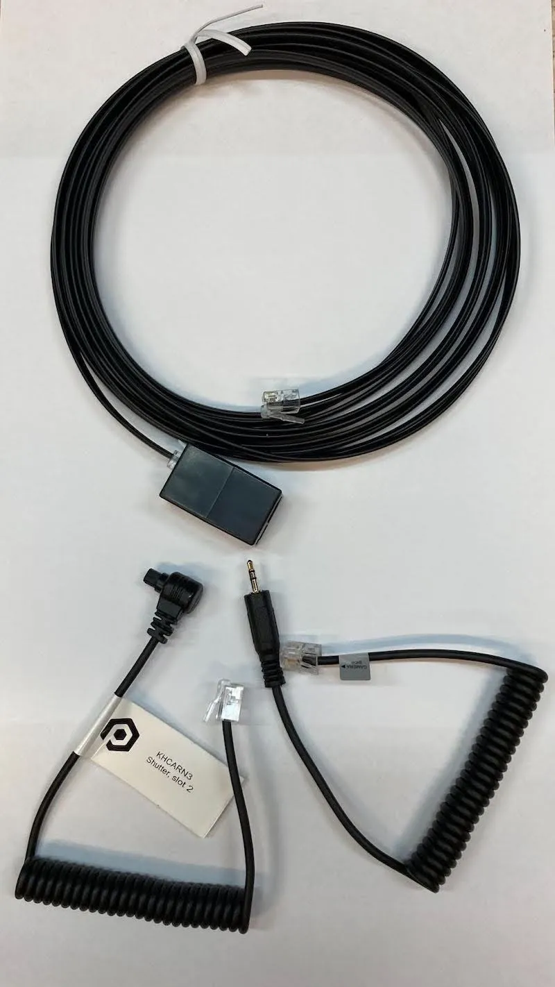
2.5.2. หากเตรียมใช้โหมดหมุนเร็ว ให้ต่อสายชัตเตอร์ (มาพร้อมกับหุ่นยนต์) เข้ากับกล้องด้านหนึ่ง และเข้ากับพอร์ต OUT ของหุ่นยนต์ C-Class อีกด้านหนึ่ง
3. PhotoRobot ใช้ครั้งแรก
ก่อนใช้งาน PhotoRobot ครั้งแรก สิ่งสําคัญคือต้องเข้าใจว่า PhotoRobot เป็นหน่วยโมดูลาร์ที่ประกอบด้วยส่วนประกอบทั้งฮาร์ดแวร์และซอฟต์แวร์ นอกจากนี้ PhotoRobot ยังเป็นระบบแบบครบวงจรเพื่อทําให้ทุกขั้นตอนของเวิร์กโฟลว์การผลิตเป็นไปโดยอัตโนมัติ ซึ่งหมายความว่าจําเป็นต้องมี PhotoRobot เองที่จะต้องเชื่อมต่อกับเครือข่ายและคอมพิวเตอร์บนเครือข่ายนั้น ด้วยเหตุนี้ เครือข่ายจึงต้องมีการเชื่อมต่ออินเทอร์เน็ตเพื่อเข้าถึงบริการ PhotoRobot
ข้อกําหนดการใช้งานพื้นฐานสําหรับ PhotoRobot มีดังนี้
- ระบบ PhotoRobot ต้องเชื่อมต่อกับเครือข่ายท้องถิ่น
- ต้องมีคอมพิวเตอร์เพื่อเรียกใช้ GUI บริการหรือซอฟต์แวร์ของผู้ปฏิบัติงาน (PhotoRobot _Controls App)
- คอมพิวเตอร์ต้องเชื่อมต่อกับเครือข่ายเดียวกันกับระบบ PhotoRobot
- ต้องมีการเชื่อมต่ออินเทอร์เน็ตผ่านเครือข่าย
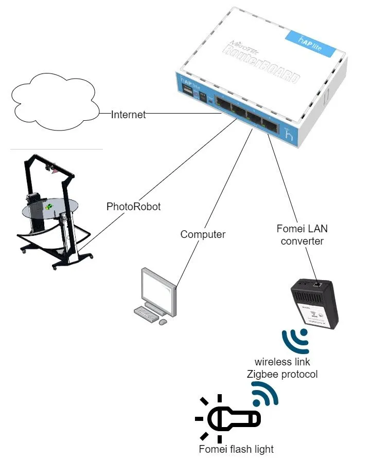
3.1. รูปแบบการเชื่อมต่อไฟแฟลช Fomei
ต่อไปนี้แสดงรูปแบบการเชื่อมต่อสําหรับไฟแฟลช Fomei หมายเหตุ ประเภทเราเตอร์อาจแตกต่างกันไปหากเคสชั้นวางมาพร้อมกับโซลูชัน PhotoRobot
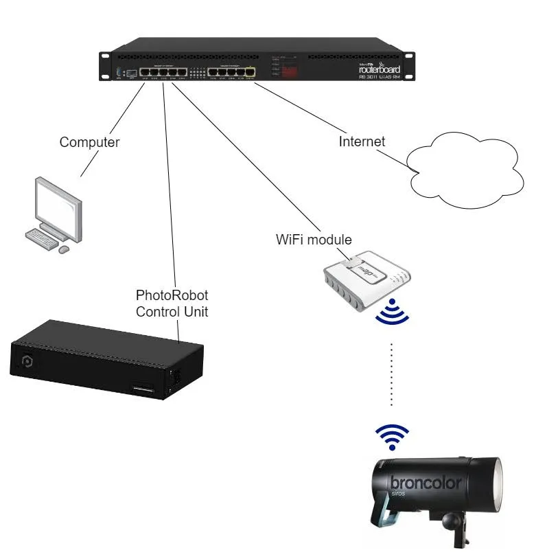
3.2. รูปแบบการเชื่อมต่อไฟแฟลช Broncolor
ใช้แผนที่ต่อไปนี้ในรูปแบบการเชื่อมต่อสําหรับไฟฉาย Broncolor โปรดทราบว่าประเภทเราเตอร์อาจแตกต่างกันไป
3.3. การเชื่อมต่ออุปกรณ์ PhotoRobot
ในการเชื่อมต่ออุปกรณ์ PhotoRobot กับเครือข่ายเพื่อการทํางานที่เหมาะสม ก่อนอื่นให้ตรวจสอบพารามิเตอร์ของระบบจําหน่ายไฟฟ้า (เช่น แรงดันไฟฟ้าและความถี่)
จากนั้นทําตามขั้นตอนต่อไปนี้เพื่อเตรียมอุปกรณ์ PhotoRobot
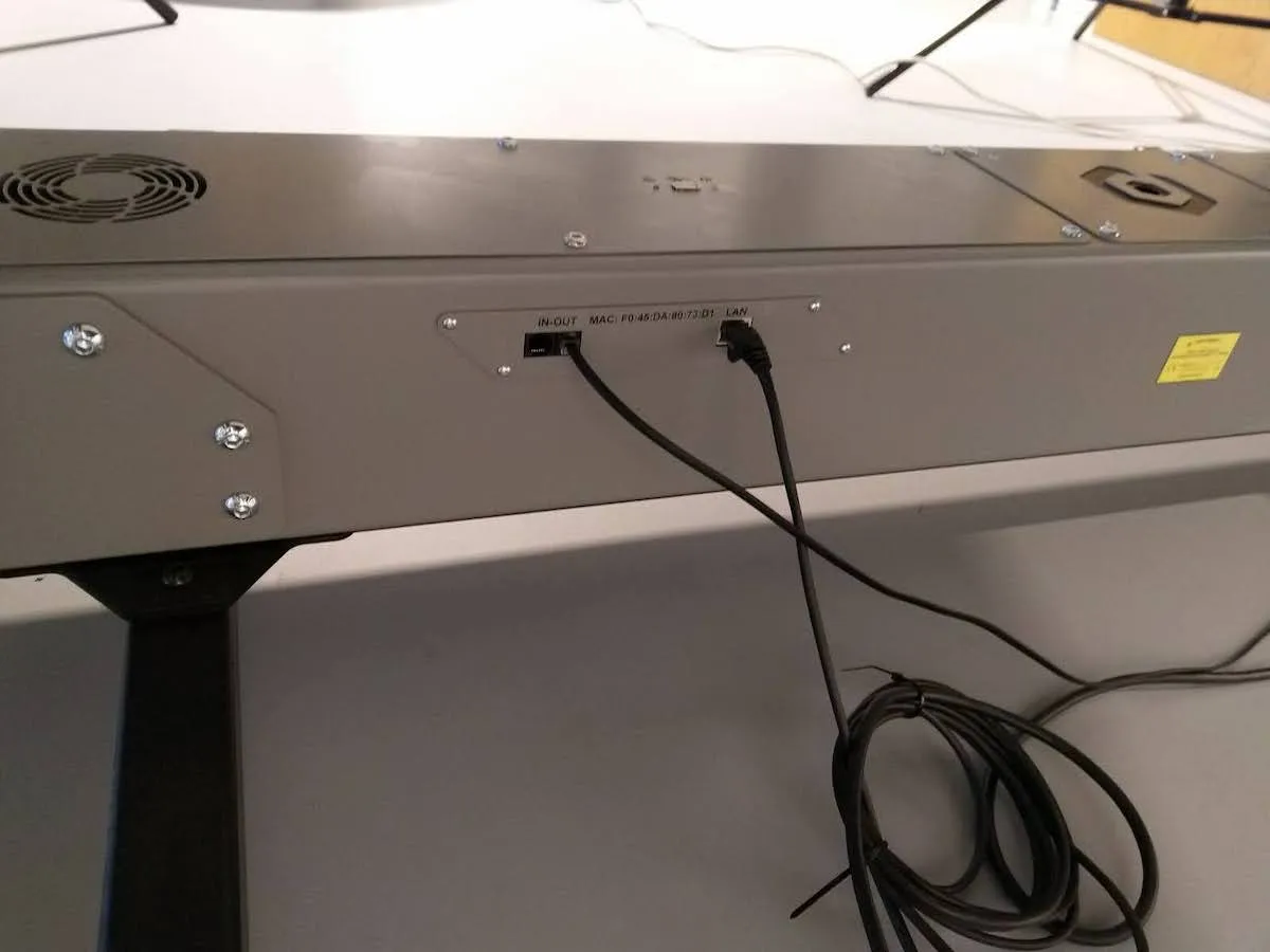
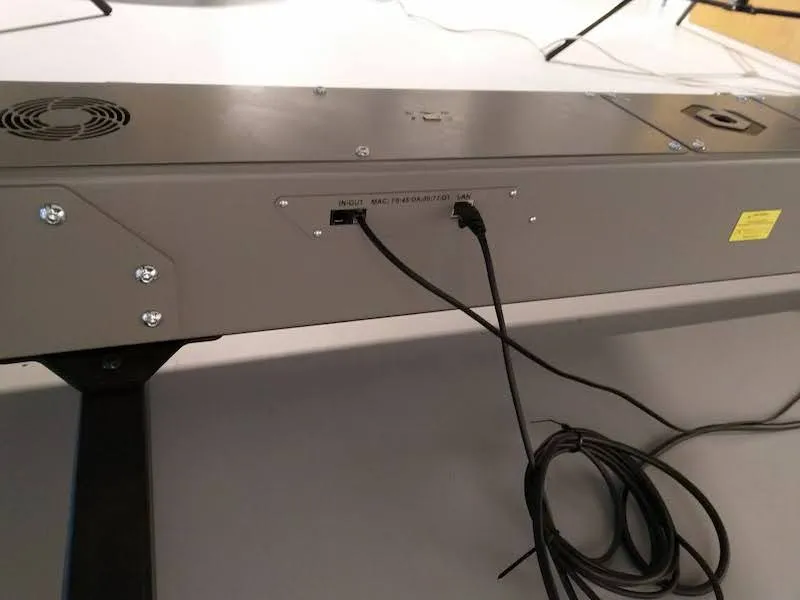
- เชื่อมต่อชุดควบคุมผ่านสายอีเทอร์เน็ตเข้ากับเราเตอร์ที่ให้มา หมายเหตุ ขั้วต่อ RJ45 อยู่ที่ด้านหลังของชุดควบคุม
- เชื่อมต่อคอมพิวเตอร์ผ่านสายอีเทอร์เน็ตเข้ากับเราเตอร์ที่ให้มา
- เชื่อมต่อเราเตอร์กับอินเทอร์เน็ต (พอร์ตหมายเลข 1)
ในการเชื่อมต่อกับเครือข่าย ให้สังเกตข้อกําหนดพื้นฐานของเครือข่ายต่อไปนี้ด้วย
- จําเป็นต้องมีเซิร์ฟเวอร์ DHCP ในเครือข่าย
- ต้องอนุญาตให้มีการสื่อสารพอร์ต TCP 80, 7777, 7778
- จําเป็นต้องมีการเชื่อมต่ออินเทอร์เน็ต
- อ้างถึงข้อกําหนดเบื้องต้นเกี่ยวกับเครือข่ายโดยละเอียดของ PhotoRobot สําหรับข้อมูลเพิ่มเติมหากจําเป็น
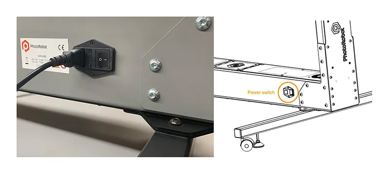
- เสียบปลั๊กไฟเข้ากับเต้ารับไฟฟ้า
- กดสวิตช์ไฟหลักบนชุดควบคุม (เมื่อเปลี่ยนสถานะจากไฟกะพริบเป็นไฟต่อเนื่อง แสดงว่าพร้อมใช้งาน)
3.4. ค้นหาที่อยู่ IP ของ PhotoRobot ผ่าน LAN
หลังจากกำหนดค่าเครือข่ายอย่างถูกต้องแล้ว จำเป็นต้องค้นหาและระบุที่อยู่ IP ของ PhotoRobot บน LAN ในการดำเนินการนี้ แอป PhotoRobot Locator ได้รับการรวมเข้ากับ CAPP โดยตรง เพื่อการค้นหาและระบุ Control Units บนเครือข่ายได้ง่ายขึ้น ตรวจสอบให้แน่ใจว่าคุณกำลังใช้ CAPP เวอร์ชันล่าสุดเพื่อเข้าถึงคุณสมบัตินี้
จากนั้น เพื่อระบุหุ่นยนต์บนเครือข่ายโดยตรงภายใน CAPP ให้เปิด CAPP เวอร์ชันโลคัล ไปที่การตั้งค่า และคลิก หุ่นยนต์ / หน่วยควบคุม
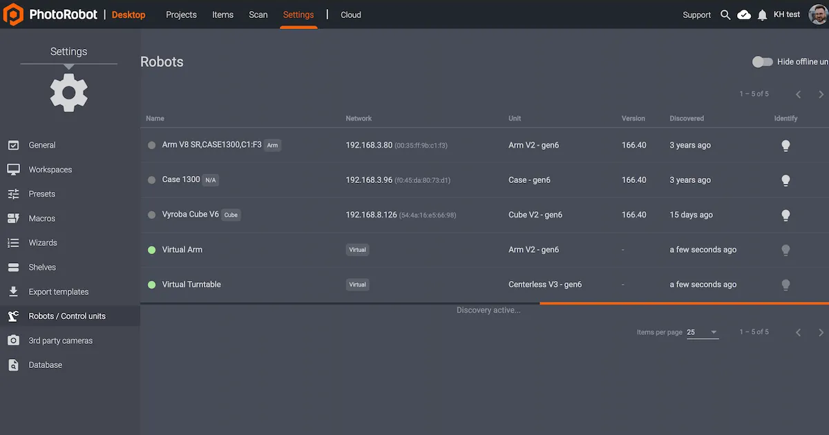
เมนู Robots / Control units จะแสดงคอลัมน์ที่มี Name, Network, Unit, Version, Discovered และ Identify สำหรับหุ่นยนต์แต่ละตัว หากจุดทางด้านซ้ายของชื่อหุ่นยนต์เป็นสีเขียว แสดงว่าหุ่นยนต์ออนไลน์ การคลิกที่ช่องหุ่นยนต์จะเปิดอินเทอร์เฟซเว็บไซต์ของหุ่นยนต์ นอกจากนี้ยังจะทำให้ไฟ LED บน Control Unit ของหุ่นยนต์กะพริบเป็นสีเขียวเพื่อให้ระบุได้ง่ายขึ้น
หากลูกค้าต้องการดาวน์โหลดแอปภายนอก PhotoRobot Locator ก็มีให้ดาวน์โหลดสำหรับ iOS ภายใน PhotoRobot Account Downloads
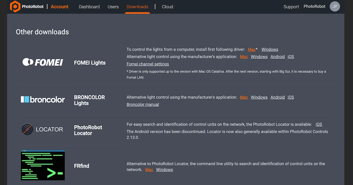
หมายเหตุ: PhotoRobot Locator เวอร์ชัน Android ได้ถูกยกเลิกแล้ว
อีกทางเลือกหนึ่งคือมียูทิลิตีบรรทัดคำสั่ง FRFind สำหรับ MacOS หรือ Windows เพื่อค้นหาเครือข่ายและระบุ PhotoRobot Control Units ค้นหาลิงก์สำหรับดาวน์โหลด FRfind ได้ที่หน้า PhotoRobot Account Downloads ด้วย
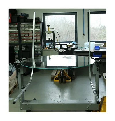
3.5. การทดสอบ PhotoRobot ขั้นพื้นฐาน
3.5.1. บนคอมพิวเตอร์ ให้เปิด web เบราว์เซอร์และป้อนที่อยู่ IP ของ PhotoRobots ใน URL รูปแบบ สิ่งนี้จะมีลักษณะเช่น: https://11.22.33.44 (อย่างไรก็ตาม โปรดทราบว่าที่อยู่นี้เป็นเพียงตัวอย่าง ให้ใช้ที่อยู่ IP ที่คุณพบในส่วนด้านบน)
3.5.2. หากสําเร็จ จะมีส่วนต่อประสานผู้ใช้พื้นฐานคล้ายกับกราฟิกด้านล่าง
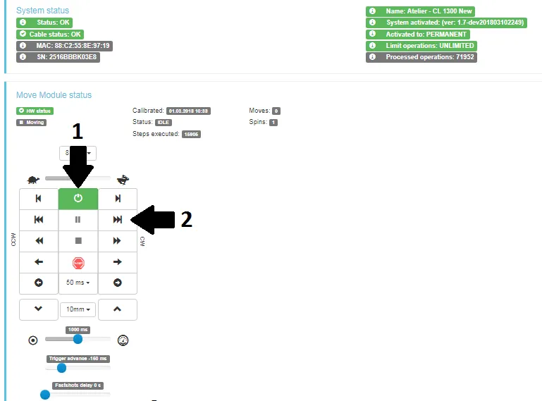
3.5.3. เปิดเครื่องยนต์ (ลูกศร 1) และพยายามใช้งานส่วนที่เคลื่อนย้ายได้ของหุ่นยนต์ (ลูกศร 2) หากการเคลื่อนไหวของหุ่นยนต์ทําตามคําแนะนําของคุณ แสดงว่าอุปกรณ์ PhotoRobot ของคุณพร้อมใช้งานเป็นประจํา


EOS Rebel ซีรีส์


EOS DSLR ซีรี่ส์


EOS M ซีรีส์มิเรอร์เลส


ซีรีส์ PowerShot


โคลสอัพ / มือถือ

Canon EOS Rebel Series นําเสนอกล้อง DSLR ที่เป็นมิตรกับผู้เริ่มต้น ด้วยคุณภาพของภาพที่มั่นคง การควบคุมที่ใช้งานง่าย และคุณสมบัติที่หลากหลาย กล้องเหล่านี้เหมาะอย่างยิ่งสําหรับผู้ที่ชื่นชอบการถ่ายภาพ ให้โฟกัสอัตโนมัติที่เชื่อถือได้ หน้าจอสัมผัสแบบปรับมุมได้ และการบันทึกวิดีโอ Full HD หรือ 4K
การเชื่อมต่อ
ความละเอียด (MP)
มติ
Canon EOS DSLR Series ให้ภาพคุณภาพสูง ออโต้โฟกัสที่รวดเร็ว และความอเนกประสงค์ ทําให้เหมาะสําหรับทั้งการถ่ายภาพและการผลิตวิดีโอ
การเชื่อมต่อ
ความละเอียด (MP)
มติ
Canon EOS M Mirrorless Series ผสมผสานการออกแบบที่กะทัดรัดเข้ากับประสิทธิภาพที่เหมือนกล้อง DSLR กล้องเหล่านี้มีเลนส์แบบเปลี่ยนได้ โฟกัสอัตโนมัติที่รวดเร็ว และเซ็นเซอร์ภาพคุณภาพสูง จึงเหมาะสําหรับนักเดินทางและผู้สร้างเนื้อหาที่ต้องการพกพาโดยไม่ลดทอนคุณภาพของภาพ
การเชื่อมต่อ
ความละเอียด (MP)
มติ
Canon PowerShot Series นําเสนอกล้องขนาดกะทัดรัดที่ใช้งานง่ายสําหรับผู้ที่ชื่นชอบการถ่ายภาพทั่วไป ด้วยรุ่นต่างๆ ตั้งแต่กล้องเล็งแล้วถ่ายภาพแบบธรรมดาไปจนถึงกล้องซูมขั้นสูง ให้ความสะดวกสบาย คุณภาพของภาพที่มั่นคง และคุณสมบัติต่างๆ เช่น ระบบป้องกันภาพสั่นและวิดีโอ 4K
การเชื่อมต่อ
ความละเอียด (MP)
มติ
กล้องโคลสอัพและกล้องมือถือของ Canon ได้รับการออกแบบมาสําหรับการถ่ายภาพและวิดีโอที่มีรายละเอียดและระยะใกล้ ขนาดกะทัดรัดและใช้งานง่าย ให้โฟกัสที่แม่นยํา การถ่ายภาพความละเอียดสูง และความสามารถด้านมาโครที่หลากหลาย เหมาะสําหรับวิดีโอบล็อก การถ่ายภาพผลิตภัณฑ์ และการถ่ายภาพระยะใกล้ที่สร้างสรรค์
การเชื่อมต่อ
ความละเอียด (MP)
มติ


